background image

4-1

4

Replaceable Parts

Summary of Contents for HP 85060B

Page 1: ...ence Guide Electronic Calibration Modules HP 85091A HP 85092A HP 85093A HP 85096A HP 85098A HP 85099A HP 85060B HP 85062B HP 85064B HP Part Number 85091 90008 Supersedes 85091 90002 Printed in USA July 1999 ...

Page 2: ...software on equipment that is not furnished by Hewlett Packard This document contains proprietary information which is protected by copyright All rights are reserved No part of this document may be photocopied reproduced or translated to another language without prior written consent of Hewlett Packard Company Restricted Rights Legend Use duplication or disclosure by the U S Government is subject ...

Page 3: ...ions 2 3 Operating Temperature and Accuracy Enhancement 2 4 Barometric Pressure and Relative Humidity 2 4 Mechanical Characteristics 2 5 Center Conductor Pin Depth 2 5 Pin Depth 2 5 Electrical Performance 2 6 Type N 50 Ω and Type N 75 Ω Connector Characteristics 2 6 Connector Pin Depth Information 2 8 Characteristics and Specifications 2 10 Measurement Port Characteristics 2 10 Supplemental Charac...

Page 4: ...leaning the Center Collet While It Is in Place 3 11 Cleaning a Removed Center Collet 3 11 Gauging Devices 3 12 Gauge Accuracy 3 12 When to Gauge Connectors 3 12 Using Connector Gauges 3 14 Recognizing Gauge Types 3 14 Making Connections 3 18 Using a Torque Wrench 3 18 Zeroing Connector Gauges 3 20 Zeroing the Gauge 3 20 Gauging Techniques 3 22 Using Male Screw on Type Gauges 3 22 Using Female Scre...

Page 5: ...1 1 1 General Information ...

Page 6: ... ECal modules and their related equipment For clarification only this manual refers to the HP 8509X family as RF modules and the HP 8506X family as microwave modules NOTE ECal modules can be controlled using an HP 85060C control unit or a combination of the HP 85097A PC interface module and a customer supplied PC Refer to the Electronic Calibration System User s Guide HP part number 85091 90007 fo...

Page 7: ...gher HP 8753E 7 12 or higher HP 8510B 6 54 HP 8510C 7 00 or higher HP 8719C 1 05 HP 8719D 6 14 or higher HP 8720C 1 05 HP 8720D 6 14 or higher HP 8722C 1 05 HP 8722D 6 14 or higher HP 8753ES 7 60 or higher HP 8753ET1 1 ET model analyzers do not have the capability to accommodate full 2 port calibrations Therefore the only ECal calibration selection valid for these analyzers is S11 1 Port which is ...

Page 8: ... case or any device appears damaged contact the nearest Hewlett Packard sales or service office listed in Service and Support on page 1 9 of this manual Hewlett Packard will arrange for repair or replacement of incomplete or damaged shipments without waiting for settlement from the transportation company Equipment Recommended but Not Supplied It is recommended that whenever possible pin depth gaug...

Page 9: ...e ECal Module Reference Guide 3 4 inch 135 N cm 12 in lb torque wrench for use on the 7 mm connectors 7 mm collet extraction tool HP 85092A Type N 50 Ω Kit 30 kHz to 6 GHz Calibration Module ECal Module Reference Guide 3 4 inch 135 N cm 12 in lb torque wrench for use on the type N 50 Ω connectors HP 85093A 3 5 mm Kit 30 kHz to 6 GHz Calibration Module ECal Module Reference Guide 20 mm 90 N cm 8 in...

Page 10: ... to male adapter Table 1 3 HP 8506X Series ECal Kit Contents Kit Model Number and Type Operating Frequency Manuals and Software Included Torque Wrench and Torque Weight Other Tools HP 85060B 7 mm Kit 1 to 18 GHz Calibration Module ECal Module Reference Guide Specification Verification Program Disks 3 4 inch 135 N cm 12 in lb torque wrench for use on the 7mm connectors 7 mm collet extraction tool H...

Page 11: ...e kit serial number the calibration modules in each kit are individually serialized For your convenience the following table has been created for you to record these serial numbers Recording the serial numbers helps maintain the integrity of your kit Kit integrity is an important part of compliance with U S MIL STD 45662A Microwave modules with serial numbers below 800 will need to be retrofitted ...

Page 12: ...son within your company and the person s complete telephone number The model number and serial number of the kit if you are returning a complete kit The part numbers and serial numbers of the devices if you are returning individual components of the kit Type of service required Any other applicable information The foam lined storage case in which the kit was shipped provides protection during ship...

Page 13: ...this product must be performed by qualified personnel Contact a customer engineer through the nearest HP service center You can find a list of HP service centers on the web at http www hp com go tmdir If you do not have access to the Internet one of these HP centers can direct you to your nearest HP representative ...

Page 14: ...am Berkshire RG41 5DZ England 44 118 9696622 INTERCON FIELD OPERATIONS Headquarters Hewlett Packard Company 3495 Deer Creek Rd Palo Alto CA 94304 1316 USA 415 857 5027 Japan Hewlett Packard Japan Ltd 9 1 Takakura Cho Hachioji Tokyo 192 Japan 81 426 60 2111 Australia Hewlett Packard Australia Ltd 31 41 Joseph Street Blackburn Victoria 3130 61 3 895 2895 Singapore Hewlett Packard Singapore Pte Ltd 1...

Page 15: ...es a hazard It calls attention to a procedure practice or the like that if not correctly performed or adhered to could result in personal injury Do not proceed beyond a WARNING notice until the indicated conditions are fully understood and met CAUTION The CAUTION notice denotes a hazard It calls attention to an operating procedure practice or the like which if not correctly performed or adhered to...

Page 16: ...s that have a laser output This symbol indicates that the instrument requires alternating current ac input The CE mark is a registered trademark of the European Community If it is accompanied by a year it indicates the year the design was proven The CSA mark is a registered trademark of the Canadian Standards Association 1SM1 A This text indicates that the instrument is an Industrial Scientific an...

Page 17: ...Chapter 1 1 13 General Information Safety and Regulatory Information ...

Page 18: ...2 1 2 Specifications and Characteristics ...

Page 19: ... maintains its specified performance while correction is turned on If this temperature range is exceeded the error corrected performance of the VNA is degraded Measurement Calibration This calibration determines the corrections necessary for accuracy enhanced correction on measurements Connector Pin Depth Values Pin depth is a relative measurement value between the center conductor and outer condu...

Page 20: ...orage Temperature 40 to 75 C 40 to 167 F Barometric Pressure Altitude 1 Operation Storage 1 It should be noted that the HP 85097A PC interface is not warranted for use above 3000 meters 10 000 feet 4 500 meters 15 000 feet 15 000 meters 50 000 feet Relative Humidity Operation Storage Non condensing at all times 0 to 80 at 26 C maximum dry bulb 0 to 95 at 26 C maximum dry bulb EMI Conducted Suscept...

Page 21: ...e made within 1 C of the error corrected operating temperature range specification of the VNA If the ambient operating temperature drift of the VNA exceeds the allowable error corrected temperature range a new measurement calibration must be performed to ensure optimum accuracy NOTE Remember that your fingers are a heat source so avoid unnecessary handling of the module connectors and cables Barom...

Page 22: ...leaves the factory Pin Depth Pin depth is the distance the center conductor mating plane differs from being flush with the outer connector mating plane see Figure 2 1 on page 2 6 The pin depth of a connector can be in one of two states either protruding or recessed NOTE No protrusion of the center conductor shoulder is allowable on any 7 mm connector when the slotted collet is removed The slotted ...

Page 23: ...et electrical specifications Type N 50 Ω and Type N 75 Ω Connector Characteristics Type N connectors differ from most other connector types in that the outer conductor mating plane is offset from the mating plane of the center conductor see Figure 2 1 The outer conductor in the male connector extends in front of the shoulder of the male contact pin When you make a connection this outer conductor f...

Page 24: ...than in the MIL C 39012 Class II specification Hewlett Packard type N pin depth gauges set zero on the gauge to be equal to a nominal 5 258 mm 0 207 inches offset As type N connectors wear the protrusion of the female contact fingers generally increases This is due to the wear of the outer conductor mating plane inside the female connector It is necessary to check this periodically as it decreases...

Page 25: ...ctory using analog gauges according to recommended procedures Table 2 4 7 mm Connector Pin Depth Limits Device Typical Pin Depth in micrometers 10 4 inches Measurement Uncertainty1 in micrometers 10 4 inches Observed Pin Depth Limits in micrometers 10 4 inches 7 mm ECal Module 25 4 to 50 8 10 0 to 20 0 1 3 to 1 3 0 5 to 0 5 24 1 to 52 1 9 5 to 20 5 1 Approximately 2 sigma to 2 sigma of gauge uncer...

Page 26: ...rved Pin Depth Limits in micrometers 10 4 inches Type N 75 Ω ECal Module 25 4 to 50 8 10 0 to 20 0 3 8 to 3 8 1 5 to 1 5 21 6 to 54 6 8 5 to 21 5 Type N 75 Ω Adapter 0 to 76 2 0 to 30 0 3 8 to 3 8 1 5 to 1 5 3 8 to 80 0 1 5 to 31 5 1 Measured from a 5 258 mm 0 207 inches nominal offset 2 Approximately 2 sigma to 2 sigma of gauge uncertainty based on studies performed at the factory using analog ga...

Page 27: ...mm ECal HP 85091A Frequency Range Residual 30 to 300 kHz typical 0 3 to 300 MHz 0 3 to 3 GHz 3 to 6 GHz Directivity dB 52 52 56 55 Source Match dB 45 45 45 42 Reflection Tracking dB 0 050 0 038 0 038 0 068 Transmission Tracking dB 0 140 0 060 0 055 0 085 Load Match dB 41 48 47 46 Table 2 8 HP 85060B Microwave 7 mm ECal HP 85060B Frequency Range Residual 1 to 2 GHz 2 to 8 GHz 8 to 18 GHz Directivit...

Page 28: ... Type N 50 Ω ECal HP 85064B Frequency Range Residual 1 to 2 GHz 2 to 8 GHz 8 to 18 GHz Directivity dB 50 49 46 Source Match dB 46 45 40 Reflection Tracking dB 0 034 0 046 0 065 Transmission Tracking dB 0 043 0 050 0 140 Load Match dB 46 44 40 Option 001 Add RF ECal Module 30 kHz to 6 GHz See HP 85092A specifications Table 2 11 HP 85093A RF 3 5 mm ECal HP 85093A Frequency Range Residual 30 to 300 k...

Page 29: ...93A specifications Table 2 13 HP 85096A RF Type N 75 Ω ECal HP 85096A Frequency Range Residual 30 to 300 kHz typical 0 3 to 300 MHz 0 3 to 1 3 GHz 1 3 to 3 GHz Directivity dB 51 50 48 43 Source Match dB 45 48 45 38 Reflection Tracking dB 0 100 0 032 0 060 0 100 Transmission Tracking dB 0 150 0 075 0 095 0 160 Load Match dB 41 43 41 39 Table 2 14 HP 85098A RF 7 16 ECal HP 85098A Frequency Range Res...

Page 30: ...ansmission Tracking dB 0 150 0 075 0 100 0 170 Load Match dB 41 43 41 39 1 Pin diameter is 0 77 mm 0 030 in to 0 86 mm 0 034 in Table 2 16 HP 85099A RF Type F ECal1 HP 85099A Frequency Range Residual 30 to 300 kHz typical 0 3 to 300 MHz typical 0 3 to 1 3 GHz typical 1 3 to 3 0 GHz typical Directivity dB 40 48 43 32 Source Match dB 37 46 41 26 Reflection Tracking dB 0 150 0 060 0 090 0 350 Transmi...

Page 31: ...300 kHz with typical performance down to 30 kHz 2 Option 001 adds an RF ECal module 30 kHz to 6 GHz to the microwave HP 8506X series ECal module 3 This is the typical power required at the port of the module used Table 2 18 Type N 7 16 and Type F ECal Module Characteristics and Specifications HP 85092A 1 HP 85064B HP 85096A1 HP 85098A 1 HP 85099A 1 Frequency Standard Option 001 1 2 30 kHz to 6 GHz...

Page 32: ...hipping Weight Standard 4 3 kilograms 9 5 lbs Shipping Dimensions Length Width Height 55 2 cm 21 75 inches 36 8 cm 14 5 inches 27 3 cm 10 75 inches Table 2 20 HP 8506X Mechanical Characteristics Characteristic Limits Net Weight With Case Standard Option 001 2 7 kilograms 5 9 lbs 3 3 kilograms 7 3 lbs Shipping Weight Standard Option 001 4 3 kilograms 9 5 lbs 4 9 kilograms 10 8 lbs Dimensions Length...

Page 33: ...listed in this table 8710 1764 20 mm 3 5 mm 90 N cm 8 in lb 9 N cm 0 8 in lb 8710 1765 5 16 in 3 5 mm 90 N cm 8 in lb 9 N cm 0 8 in lb 8710 1766 3 4 in 7 mm 135 N cm 12 in lb 13 5 N cm 1 2 in lb 8710 1766 3 4 in Type N 50 Ω 135 N cm 12 in lb 13 5 N cm 1 2 in lb 8710 17663 3 Recommended but not supplied with the HP 85096A 3 4 in Type N 75 Ω 135 N cm 12 in lb 13 5 N cm 1 2 in lb 8710 2174 1 1 16 in ...

Page 34: ...e travel areas Outside HP service travel areas warranty service will be performed at Buyer s facility only upon HP s prior agreement and Buyer shall pay HP s round trip travel expenses In all other areas products must be returned to a service facility designated by HP For products returned to HP for warranty service Buyer shall prepay shipping charges to HP and HP shall pay shipping charges to ret...

Page 35: ...MEDIES HP SHALL NOT BE LIABLE FOR ANY DIRECT INDIRECT SPECIAL INCIDENTAL OR CONSEQUENTIAL DAMAGES WHETHER BASED ON CONTRACT TORT OR ANY OTHER LEGAL THEORY Assistance Product maintenance agreements and other customer assistance agreements are available for Hewlett Packard products For assistance call the nearest Hewlett Packard sales or service office refer to Service and Support on page 1 9 ...

Page 36: ...3 1 3 Gauging and Making Connections ...

Page 37: ...reat care Their continued performance and accuracy are dependent upon maintaining the precise mechanical tolerances of the connectors When the calibration modules are not in use replace their protective end caps and store them in the foam lined storage case The storage case lid is detachable so that the case can be stored in a drawer ...

Page 38: ...to any static sensitive circuits on the calibration module or any instrument it is essential to protect against ESD Always have a grounded antistatic mat in front of your test equipment and wear a grounded wrist strap attached to it See Figure 3 1 on page 3 4 Ground yourself before you clean inspect or make a connection to a static sensitive device or test port You can for example grasp the ground...

Page 39: ...3 4 Chapter3 Gauging and Making Connections Electrostatic Discharge ESD Figure 3 1 ESD Protection Using Mat Wrist Strap and Grounded Power Cord ...

Page 40: ...move dirt or metallic particles on a connector mating plane surface can degrade repeatability and accuracy and can damage any connector mated to it Improper connections resulting from pin depth values being out of the Observed Pin Depth Limits see Table 2 3 through Table 2 8 or from using poor connection techniques can also damage these devices Visual inspection cleaning and proper connection tech...

Page 41: ... and be free of burrs loose metal particles and rough spots Devices with damaged connectors should be discarded or repaired if possible Try to determine the cause of damage before connecting a new undamaged connector in the same configuration Inspecting the Mating Plane Surfaces Flat contact between the connectors at all points on their mating plane surfaces is required for a good connection Look ...

Page 42: ...important when you are mating nonprecision to precision devices Checking for Connector Wear Connector wear eventually degrades performance The more use a connector gets the faster it wears and degrades This is especially true with electrically characterized devices such as ECal modules The wear is greatly accelerated when connectors are not kept clean or are connected incorrectly Test port connect...

Page 43: ...clean and free of residue If not do not use the alcohol from that container Whenever you need to clean connectors pour a small amount of alcohol into a clean container to use this will keep your main supply of alcohol free of contamination When you have finished cleaning the connectors safely discard any remaining alcohol and clean the container WARNING Isopropyl alcohol is extremely flammable cau...

Page 44: ... Cleaning the Connector Threads CAUTION This procedure assumes you have taken the necessary ESD precautions Refer to Electrostatic Discharge ESD on page 3 3 for a description of ESD precautions For dirt or stubborn contaminants on a connector that you cannot remove with compressed air or nitrogen try a cleaning swab or lint free cleaning cloth moistened with isopropyl alcohol To clean the connecto...

Page 45: ...he center conductor contact fingers Drying the Connector After cleaning blow the connector dry with a gentle stream of clean compressed air or nitrogen Always completely dry a connector before you reassemble or use it Inspecting Each Connector Again Inspect the connector again under a magnifying glass to be sure that no particles or residues remain ...

Page 46: ...ate the connector The cloth scrubs away dirt on the connector interface without damaging it 5 Blow the connector dry with a gentle stream of compressed air or nitrogen 6 When not in use keep the cloth in a plastic bag or box so that it does not collect dust or dirt For fixed connectors connectors attached to a device that cannot be freely moved 1 Fold a lint free cleaning cloth several times 2 Moi...

Page 47: ... associated with pin depth measurements At the factory with special gauging processes and electrical testing the mechanical characteristics of devices can be accurately verified Even then the resultant average can be in error by as much as 0 0001 inch due to systematic biasing errors usually resulting from worn gauges and gauge masters As a result these systematic errors are not included in the un...

Page 48: ...ctions and after that as often as experience suggests NOTE When using the 7 mm ECal Kit module you must remove the 7 mm collet before gauging the pin depth of the connectors Refer to Gauging Techniques on page 3 22 for gauging instructions Use the collet extraction tool provided in your 7 mm kit to remove the collet ...

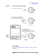
Page 49: ...connector uses a different connector gauge For detailed descriptions of connector gauges See Figure 3 2 on page 3 15 for typical 3 5 mm gauges See Figure 3 3 on page 3 16 for typical 7 mm gauges See Figure 3 4 on page 3 17 for typical type N gauges The gauges in all of the kits are screw on type gauges Every connector gauge requires a gauge calibration block to zero the gauge A gauge is referred t...

Page 50: ...Chapter 3 3 15 Gauging and Making Connections Using Connector Gauges Figure 3 2 Typical 3 5 mm Connector Gauge ...

Page 51: ...3 16 Chapter3 Gauging and Making Connections Using Connector Gauges Figure 3 3 Typical 7 mm Connector Gauge ...

Page 52: ...Chapter 3 3 17 Gauging and Making Connections Using Connector Gauges Figure 3 4 Typical Type N Connector Gauge ...

Page 53: ...sive torque to the RF connectors Do not exceed the recommended specifications listed on Torque Wrench Information on page 2 16 when connecting and disconnecting RF ECal modules Using a Torque Wrench 1 Hand tighten the connection to be torqued Be sure to keep the connectors from rotating relative to each other Turn the coupling nut only CAUTION Rotating connectors relative to each other during the ...

Page 54: ...Chapter 3 3 19 Gauging and Making Connections Making Connections Figure 3 5 Proper and Improper Torquing Methods ...

Page 55: ...6 and Figure 3 4 on page 3 17 NOTE Hold a connector gauge by the gauge barrel below the dial indicator This gives the best stability and improves measurement accuracy Cradling the gauge in your hand or holding it by the dial applies stress to the gauge plunger mechanism through the dial indicator housing Zeroing the Gauge 1 Select the proper gauge for your connector Always use gauges which are int...

Page 56: ... appropriate torque wrench to tighten the connecting nut of the gauge master c As you watch the gauge pointer gently tap the barrel of the gauge to settle the reading The gauge pointer should line up exactly with the zero mark on the gauge If not clean and inspect both the gauge and gauge master If the gauge and gauge master are clean and free from defects adjust the zero set knob until the gauge ...

Page 57: ...ding the gauge by the barrel Tighten the nut finger tight without turning the gauge or calibration module 2 Torque the connector to the appropriate torque value for the connector supplied see Torque Wrench Information on page 2 16 3 Gently tap the barrel of the gauge with your finger to settle the reading 4 Measure the connector a minimum of three times then average the readings for maximum accura...

Page 58: ... the needle has moved clockwise the center conductor is protruding and the value is determined by the black numbers If the needle has moved counterclockwise the center conductor is recessed by an amount determined by the red numbers 7 mm Gauge CAUTION You must remove the collet with the collet extractor tool prior to performing pin depth measurements Figure 3 6 Using a 7 mm Connector Gauge While p...

Page 59: ...ush the connectors straight together Do not twist or screw them together 5 Engage the connector nut over the threads on the second connector Turn only the connector nut Let the connector nut pull the two connectors straight together NOTE At this point you want a connection in which the outer conductors make gentle contact at all points on both mating surfaces This requires very light finger pressu...

Page 60: ...Chapter 3 3 25 Gauging and Making Connections Gauging Techniques Figure 3 7 Using a Type N Connector Gauge 3 5 mm Gauge See Connecting Type N and 3 5 mm Gauges on page 3 27 for more information ...

Page 61: ...3 26 Chapter3 Gauging and Making Connections Gauging Techniques Figure 3 8 Using a 3 5 mm Connector Gauge ...

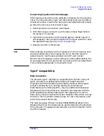
Page 62: ... wrench HP part number 8710 1770 or the spanner wrench HP part number 08513 20014 The torque supplied by the torque wrench can change with use Recalibrate it at a schedule appropriate to its amount of use Type F Compatibility Male connectors The precision type F interface is compatible with the entire range of type F connectors as defined by the Society of Cable Television Engineer s SCTE Interfac...

Page 63: ...ale conductor without compromising subsequent electrical performance with the 0 77 to 0 86 mm 0 030 to 0 034 in diameter male conductor or degrade the electrical contact with the 0 56 mm 0 022 in diameter male conductor CAUTION Many type F feedthrough connectors use the cable center conductor as the male pin These cable center conductors often exceed the 1 07 mm 0 042 in maximum pin specification ...

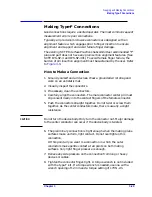
Page 64: ...necessary clean the connectors 4 Carefully align the connectors The male connector center pin must slip concentrically into the contact fingers of the female connector 5 Push the connectors straight together Do not twist or screw them together As the center conductors mate there is usually a slight resistance CAUTION Do not turn the device body Only turn the connector nut Major damage to the cente...

Page 65: ...3 30 Chapter3 Gauging and Making Connections Making Type F Connections Figure 3 9 Type F Female Connectors ...

Page 66: ...s and connections 1 Use an open end wrench to prevent the device body from turning 2 Use another open end wrench to loosen the connector nut 3 Complete the separation by hand turning only the connector nut CAUTION Turn the connector nut not the device body Major damage to the center conductor can occur if the device body is twisted 4 Pull the connectors straight apart without twisting or bending ...

Page 67: ...4 1 4 Replaceable Parts ...

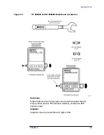
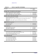
Page 68: ...with Male Male Connectors 85062B Option 001 and 00M or 85093A Option 00M Module with Female Female Connectors 85062B Option 01F or 85093A Option 00F 1 1 1 85093 60001 85093 60002 85093 60003 Adapters added with Option 00A 3 5 mm Female Female 3 5 mm Male Male 1 1 85052 60012 85052 60014 Protective End Caps DB 25 Multi pin Connector Cap 3 5 mm Female Connector Cap for 3 5 mm adapter 3 5 mm Male Con...

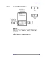
Page 69: ... HP 85093A and HP 85062B Modules and Accessories Not Shown Module Reference Guide Storage Case Specification Verification Program Disk Option 00F female to female and Option 00M male to male Adapters Adapters shown are available with Option 00A ...

Page 70: ...1 1 1 85092 60001 85092 60002 85092 60003 Adapters added with Option 00A Type N Female Female Type N Male Male 1 1 85054 60037 85054 60038 Protective End Caps DB 25 Multi pin Connector Cap Type N Female Connector Cap Type N Male Connector Cap 1 1 1 1252 4690 1401 0247 1401 0248 Other 3 4 in 135 N cm 12 in lb Torque Wrench Standard Specification Verification Program Disk only with HP 85064B Electro...

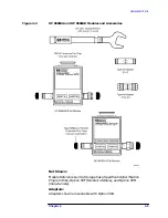
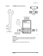
Page 71: ... HP 85092A and HP 85064B Modules and Accessories Not Shown Module Reference Guide Storage Case Specification Verification Program Disk Option 00F female to female and Option 00M male to male Adapters Adapters shown are available with Option 00A ...

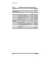
Page 72: ...96 60003 Adapters added with Option 00A Type N Female Female Type N Male Male 1 1 85036 60014 85036 60013 Protective End Caps DB 25 Multi pin Connector Cap Type N Female Connector Cap Type N Male Connector Cap 1 1 1 1252 4690 1401 0247 1401 0248 Other Electronic Calibration Module Reference Guide Connector Care Quick Reference Card 1 1 85091 90008 08510 90360 Items Not Included in Kits Screw on Ty...

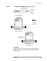
Page 73: ...ure 4 3 HP 85096A Module and Accessories Not Shown Module Reference Guide Storage Case Specification Verification Program Disk Option 00F female to female and Option 00M male to male Adapters Adapters shown are available with Option 00A ...

Page 74: ...F 1 1 1 85098 60001 85098 60002 85098 60003 Adapters added with Option 00A 7 16 Female Female 7 16 Male Male 1 1 11906 80016 11906 80015 Protective End Caps DB 25 Multi pin Connector Cap 7 16 Male Connector Cap 7 16 Female Connector Cap 1 1 1 1252 4690 1401 0417 1401 0418 Other 1 1 16 in 226 N cm 20 in lb Torque Wrench Standard Electronic Calibration Module Reference Manual Connector Care Quick Re...

Page 75: ...ure 4 4 HP 85098A Module and Accessories Not Shown Module Reference Guide Storage Case Specification Verification Program Disk Option 00F female to female and Option 00M male to male Adapters Adapters shown are available with Option 00A ...

Page 76: ...99 60003 Adapters added with Option 00A Type F Female Female Type F Male Male 1 1 85039 60002 85039 60006 Protective End Caps DB 25 Multi pin Connector Cap Type F Female Connector Cap Type F Male Connector Cap 1 1 1 1252 4690 1401 0296 1401 0297 Other 12 mm Open ended Wrench Electronic Calibration Module Reference Manual Connector Care Quick Reference Card Pin Gauge attached to module see Figure 4...

Page 77: ...gure 4 5 HP 85099A Module and Accessories Not Shown Module Reference Guide Storage Case Specification Verification Program Disk Option 00F female to female and Option 00M male to male Adapters Adapters shown are available with Option 00A ...

Page 78: ... Cap 1 1 1252 4690 1401 0249 Other 3 4 mm 135 N cm 12 in lb Torque Wrench Standard 7 mm Collet Extractor Tool Specification Verification Program Disk only with HP 85060B Electronic Calibration Module Reference Manual Connector Care Quick Reference Card 1 1 1 1 1 8710 1766 5060 0370 08510 10033 85091 90008 08510 90360 Items Not Included in 7 mm ECal Kits Screw on 7 mm Pin Depth Gauge 7 mm Repair Ki...

Page 79: ...eplaceable Parts Figure 4 6 HP 85091A and HP 85060B Modules and Accessories Not Shown Module Reference Guide Storage Case Specification Verification Program Disk Option 00F female to female and Option 00M male to male ...

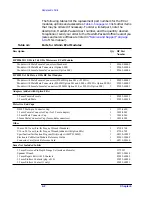
Page 80: ... 8500 6659 99 5 Isopropyl Alcohol 8 oz 8 oz 8500 0559 99 5 Isopropyl Alcohol 30 ml 30 ml 8500 5344 Cleaning Swabs 100 9301 1243 Lint free Cleaning Cloth 150 9310 4242 ESD Supplies Grounding Wrist Strap 1 9300 1367 5 ft Wrist strap to Table mat Grounding Cord 1 9300 0980 2 x 4 ft Conductive Table Mat with 15 ft Ground Wire 1 9300 0797 ESD Heel Strap 1 9300 1126 ...

Page 81: ...es 3 22 intent 3 12 type N female 3 24 type N connector 3 17 types 3 14 gauging 3 1 electrostatic discharge 3 3 handling and storage 3 2 techniques 3 22 when 3 12 gauging devices 3 12 general information 1 1 I initial connection 3 18 inspection 1 4 M making connections 3 1 electrostatic discharge 3 3 handling and storage 3 2 mechanical characteristics center conductor protrusion 2 5 pin depth 2 5 ...

Reviews: