


Chapter 1
1-5
General Information
HP 8509X Series Module ECal Kit Contents
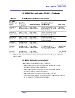
HP 8509X Series Module ECal Kit Contents
HP 8509X Series Options Available
These options do not apply to the HP 85091A.
• Option 00M replaces the standard male and female module
connectors with two male connectors.
• Option 00F replaces the standard male and female module
connectors with two female connectors.
• Option 00A adds one male-to-male adapter, and one
female-to-female adapter. A torque wrench is added to the 3.5 mm
kit for use with the male-to-male adapter.
Table 1-2
HP 8509X Series Module ECal Kit Contents
Kit Model
Number and
Type
Operating
Frequency
1
Manuals Included
Torque Wrench and
Torque Weight
Other Tools
HP 85091A,
7 mm Kit
30 kHz to 6 GHz
Calibration Module
ECal Module
Reference Guide
3/4 inch, 135 N-cm (12 in-lb)
torque wrench for use on the
7 mm connectors
7 mm collet
extraction tool
HP 85092A,
Type-N 50
Ω
Kit
30 kHz to 6 GHz
Calibration Module
ECal Module
Reference Guide
3/4 inch, 135 N-cm (12 in-lb)
torque wrench for use on the
type-N 50
Ω
connectors
HP 85093A,
3.5 mm Kit
30 kHz to 6 GHz
Calibration Module
ECal Module
Reference Guide
20 mm, 90 N-cm (8 in-lb)
torque wrench for use on the
3.5 mm connectors
HP 85096A,
Type-N 75
Ω
Kit
30 kHz to 3.0 GHz
Calibration Module
ECal Module
Reference Guide
HP 85098A,
7-16 Kit
30 kHz to 7.5 GHz
Calibration Module
ECal Module
Reference Guide
1 1/16 inch, 226 N-cm
(20 inch-lb) torque wrench for
use on the 7-16 connectors
15/16 inch open
end wrench
HP 85099A,
Type-F Kit
30 kHz to 3.0 GHz
Calibration Module
ECal Module
Reference Guide
12 mm open end
wrench
1. RF ECal kits have specified performance from 300 kHz, but will operate with typical performance
down to 30 kHz.


