background image

14. Remove the disk drive drawer.

Replacing the D6020 hard drive drawer

Procedure

1.

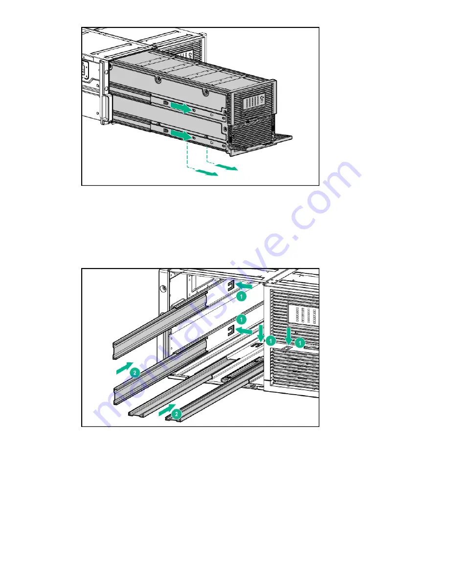
Slide the rails back into the chassis.

Figure 3: Sliding the rails back into the chassis

2.

Align the top right edge of the drawer with the flange at the top of the chassis, and align the four rails on the left
side and bottom of the drawer bay.

Removal and replacement procedures

23

Summary of Contents for HPE D6020

Page 1: ...e Part Number 839754 004 Published December 2019 Edition 4 Abstract This guide provides details on maintaining and servicing the HPE D6020 chassis The guide is intended for use by HPE support personnel who are familiar with this or similar storage systems ...

Page 2: ...ter Software Computer Software Documentation and Technical Data for Commercial Items are licensed to the U S Government under vendor s standard commercial license Links to third party websites take you outside the Hewlett Packard Enterprise website Hewlett Packard Enterprise has no control over and is not responsible for information outside the Hewlett Packard Enterprise website Acknowledgments In...

Page 3: ...luggable I O module 14 Removing and replacing the I O module blank 15 Removing and replacing the D6020 power supply 16 Removing and replacing the D6020 power block 17 Removing and replacing the D6020 disk drive drawer 21 Removing the D6020 disk drive drawer 21 Replacing the D6020 hard drive drawer 23 Component identification 26 Front panel components 26 Front panel LEDs and buttons 27 Rear panel c...

Page 4: ...lure of another drive during rebuild 45 Recovering from a power failure reported from the backplane 45 Specifications 46 Environmental specifications 46 Storage array specifications 47 Websites 48 Support and other resources 49 Accessing Hewlett Packard Enterprise Support 49 Accessing updates 49 Remote support 50 Warranty information 50 Regulatory information 50 Documentation feedback 51 4 ...

Page 5: ...s day delivery Same day or four hour delivery may be offered at an additional charge where geography permits If assistance is required you can call the HPE Technical Support Center and a technician will help you over the telephone HPE specifies in the materials shipped with a replacement CSR part whether a defective part must be returned to HPE In cases where it is required to return the defective...

Page 6: ...Power block assembly 689128 001 Optional 5 Chassis N A N A 6 Hard drive drawer 828614 001 Optional 7 Bracket kit left and right 461632 001 Mandatory Rackmount kit 432461 001 Mandatory Hard drive blank 389015 001 Mandatory Hard drive 2 Not shown 1 See Customer self repair 2 See the HPE D6020 QuickSpecs for specific and compatible hard drives at https h20195 www2 hpe com v2 getdocument aspx docname ...

Page 7: ...ype of damage may reduce the life expectancy of the device Avoid hand contact by transporting and storing products in static safe containers Keep electrostatic sensitive parts in their containers until they arrive at static free workstations Place parts on a grounded surface before removing them from their containers Avoid touching pins leads or circuitry Always be properly grounded when touching ...

Page 8: ...be required to help align the chassis if the chassis is installed higher than chest level Install the chassis starting from the bottom of the rack and then work your way up the rack To reduce the risk of personal injury from hot surfaces allow the drives and the internal system components to cool before touching them To reduce the risk of electric shock or damage to the equipment never reach insid...

Page 9: ...luminated green and are not blinking continue to step 5 b If the LEDs are not green or are blinking resolve the issue and then continue to step 5 For more information see Troubleshooting 5 Power up the nodes For more information see the documentation for your specific node Powering down the D6020 Be sure that the partner nodes are the first units to be powered down and the last to be powered back ...

Page 10: ... speed to cool down the system Prerequisites Verify that all I O bays contain either an I O module or an I O blank If I O bays are empty then the disk drive drawer does not open Verify that the I O modules or I O blanks are fully seated and their handles are in the locked position If I O modules or I O blanks are not fully seated with their handles in the locked position then the disk drive drawer...

Page 11: ...cooling and thermal damage do not operate the D6020 unless all bays are populated with either a disk drive or drive blank Remove a blank only if a drive is ready to install or the D6020 is powered down Procedure 1 Extend the disk drive drawer 2 Remove the disk drive or drive blank Removal and replacement procedures 11 ...

Page 12: ...drive LEDs and disk drive LED combinations see Disk drive LED combinations Confirm the RAID status and configuration to be sure that data loss does not occur if the drive is removed For more information see the HPE Smart Storage Administrator User Guide on the HPESC website Be sure that the replacement disk drive is the same interface and the same or larger capacity Procedure 1 Extend the disk dri...

Page 13: ... drive lever b Push the disk drive or drive blank all the way into the drive bay c Close the lever Removing and replacing the D6020 fan IMPORTANT Remove the power cord before removing the fan in accordance with the power cord label on power cord part number 142263 004 Removal and replacement procedures 13 ...

Page 14: ...tem is powered on More than one component or blank is removed After removing an active component promptly replace it with a blank or the appropriate component Procedure 1 Make sure that the disk drive drawer is closed 2 Remove the fan 3 To replace the fan a Insert the fan in to the fan bay b Push until the fan locks into place Removing and replacing the hot pluggable I O module Prerequisites Verif...

Page 15: ...le by pushing the I O handle down until it ejects the I O module and then remove the I O module 3 To replace the component reverse the removal procedure Be sure that the I O module is fully seated and the I O module handle is in the locked position Removing and replacing the I O module blank Prerequisites For best cooling practices do not operate the enclosure for more than 10 minutes when The sys...

Page 16: ...nt Ensure that all other power supplies are installed and their LEDs are illuminated green Verify the status of the power supply to be replaced by reviewing rear panel LEDs and buttons see Rear panel components Be sure that your configuration can support your actions If the proper redundancy is not in place power down the D6020 before beginning this procedure Procedure 1 Disconnect the AC power co...

Page 17: ...ies see Removing and replacing the D6020 power supply 4 Remove all fan modules see Removing and replacing the D6020 fan 5 Remove all I O modules see Removing and replacing the hot pluggable I O module 6 Release the disk drive drawers a Pull down the handle on the front of the drawer but do not extend the drawer b Push up and hold the two release mechanisms on the I O bays Removal and replacement p...

Page 18: ...e screw securing the power block to the chassis 1 b Press down on the release lever 2 c Slowly pull out the power block 3 2 54 cm to 5 08 cm 1 in to 2 in Do not remove the power block any further because the cable management arm is still attached 18 Removal and replacement procedures ...

Page 19: ...Pull the mechanism up and then toward the rear of the chassis to disengage it from the locking plate b Slide the cable management arm off both locking plates 9 Slowly remove the power block The signal and power cables are still attached Removal and replacement procedures 19 ...

Page 20: ... 11 To replace the component reverse the removal procedure 12 Power on the system as follows a Make sure that only the primary I O module is inserted b Power on the system c Wait until the primary I O module is ready less than 1 minute d Insert the secondary I O module 20 Removal and replacement procedures ...

Page 21: ...avoid data loss be sure that the drives are labeled and returned to the same bays from which they were removed 6 Make sure that the disk drive drawer is closed completely 7 Remove all I O modules see Removing and replacing the hot pluggable I O module 8 Pull down the handle on the front of the drawer but do not extend the drawer 9 Push up and hold the two release mechanisms on the I O bays and the...

Page 22: ...t a time To reduce the risk of electric shock or damage to the equipment Never reach inside the chassis while the system is powered up Perform service on system components only as instructed in the user documentation 12 Compress the cable management arm and push toward the drawer to lock it into place 13 Push in to release the four locking mechanisms on the rails located on the side and bottom of ...

Page 23: ... 1 Slide the rails back into the chassis Figure 3 Sliding the rails back into the chassis 2 Align the top right edge of the drawer with the flange at the top of the chassis and align the four rails on the left side and bottom of the drawer bay Removal and replacement procedures 23 ...

Page 24: ...of the chassis NOTE To avoid damage to the equipment HPE recommends using two people to perform this step Figure 5 Releasing and expanding the cable management arm 5 Push the drawer in another 25 cm 10 in 6 Install the power block see Removing and replacing the D6020 power block WARNING Pinch hazard Keep hands out of front and rear of chassis when closing hard drive drawers 7 Install the hard driv...

Page 25: ...tall all rear panel components 10 Connect the cables 11 Power on the system in the following manner a Make sure only the primary I O module is inserted b Power on the system c Wait until the primary I O module is ready less than 1 minute d Insert the secondary I O module Removal and replacement procedures 25 ...

Page 26: ...anel components Item Description 1 Drawer 1 2 Drawer 1 diagnostic cable access For use by authorized HPE personnel only 3 Drawer 2 4 Drawer 2 diagnostic cable access For use by authorized HPE personnel only 26 Component identification ...

Page 27: ...Front panel LEDs and buttons Component identification 27 ...

Page 28: ...ive as soon as possible Amber A drive failure link failure or mismatched configuration has occurred Off The drive is offline a spare or not configured as part of an array Hard drive LEDs Drive Locate mode UID LED is solid Green The drive is selected by a management application and operating normally Flashing amber 1 Hz The drive is not selected and is indicating a predictive failure Flashing amber...

Page 29: ...and AC power cables to the power supplies Off The enclosure is functioning normally Rear panel components 1 2 3 4 5 6 7 8 9 10 11 12 13 14 15 16 17 18 19 20 22 21 Item Description 1 Power supply 1 2 Power On UID 2 status panel 3 Fan module 1 Drawer 2 4 Primary I O module Drawer 2 5 SAS port 1 connector Drawer 2 6 SAS port 2 connector Drawer 2 7 Power supply 3 Table Continued Component identificati...

Page 30: ...ort 2 connector Drawer 1 13 SAS port 1 connector Drawer 1 14 SAS port 2 connector Drawer 1 15 Secondary I O module Drawer 1 16 Fan module 2 Drawer 1 17 Power supply 4 18 SAS port 1 connector Drawer 2 19 SAS port 2 connector Drawer 2 20 Secondary I O module Drawer 2 21 Fan module 2 Drawer 2 22 Power supply 2 30 Component identification ...

Page 31: ... supply LEDs and AC power cables to the power supplies To view any GSI error codes on the rear display activate the associated drawer UID button Off Enclosure is functioning normally 3 Internal Health LED Green System health is good Off System is off 4 UID button LED Drawer 2 Blue UID LED is enabled from the UID button Blue solid System is in disk drive Locate mode or an enclosure firmware update ...

Page 32: ...rent limit 6 System fan LED Green Normal operation Amber flashing Fault Off Fan unseated from connector or failed 7 7 segment display For more information see 7 segment display status codes and actions 8 UID button LED Drawer 1 Blue UID LED is enabled from the UID button Blue solid System is in hard drive Locate mode or an enclosure firmware update is in progress Off UID LED is disabled Table Cont...

Page 33: ...er Link at low speed with activity Green off solid amber No link or no cable connected 10 11 12 I O module LED Blue off green off amber off Power Blue off solid green amber off Healthy Flashing blue green off solid amber Faulty Locate mode Do not remove Solid blue green off solid amber Faulty Locate mode Safe to remove Solid or flashing blue solid green amber off Manual locate Safe to remove Devic...

Page 34: ...pplication On Amber flashing regularly 1 Hz A predictive failure alert has been received for this drive Replace the drive as soon as possible On Off The drive is online but it is not currently active Flashing regularly 1 Hz Amber flashing regularly 1 Hz CAUTION Do not remove the drive Removing a drive may terminate the current operation and cause data loss The drive is part of an array that is und...

Page 35: ...rly 1 Hz The drive is active but a predictive failure alert has been received for this drive Replace the drive as soon as possible Flashing irregularly Off The drive is active and operating normally Off Steadily amber A critical fault condition has been identified for this drive and the controller has placed it offline Replace the drive as soon as possible Off Amber flashing regularly 1 Hz A predi...

Page 36: ...conds 3 Ensure that the power supplies are working properly 4 Verify the status by inspecting the power supply LEDs see Rear panel components 5 Remove all AC power cords from enclosure power supplies and reinsert them 6 Restart the system see Powering up the D6020 and Powering down the D6020 7 Inspect the D6020 for the following normal power up sequence to verify that the system meets the minimal ...

Page 37: ...nd fully seated Be sure that all pins on the connectors and components are straight Contact an authorized service provider for assistance see Accessing Hewlett Packard Enterprise Support Fan LED is off The fan might not be inserted properly it might have a damaged connector or it might have failed Be sure that the fan is undamaged and fully seated Be sure that all pins on the connectors and compon...

Page 38: ...mately 3 seconds Be sure that the power supply is undamaged and fully seated Be sure that all pins on the connectors and components are straight Be sure that all components are fully seated Flash the controller firmware Contact an authorized service provider for assistance see Accessing Hewlett Packard Enterprise Support 7 segment display status codes and actions The 7 segment display shows two ty...

Page 39: ... B1 Expander bootstrap task has failed Reseat I O module If the problem persists contact support B3 Using default SAS address Reseat the I O module Reseat the backplane Power cycle the enclosure Replace the I O module Replace the backplane B5 Communication error with the partner expander Reseat the I O module Reseat the other I O module Replace the I O module Replace the other I O module B6 Expand...

Page 40: ... O module C3 Warning temperature reached in temperature sensor Verify if the environment is temperature compliant C4 Critical temperature reached in temperature sensor Verify if the environment is temperature compliant C5 Minimum temperature reached in temperature sensor Verify if the environment is temperature compliant C6 Fans commanded to maximum speed Verify if the environment is temperature c...

Page 41: ...Power Supply Module 4 Reseat the power supply Replace the power supply DA Power loss Power Supply Module 1 Verify that the AC cable is well connected to the power supply DB Power loss Power Supply Module 2 Verify that the AC cable is well connected to the power supply DD Power loss Power Supply Module 3 Verify that the AC cable is well connected to the power supply DE Power loss Power Supply Modul...

Page 42: ...ring from a power failure reported from the backplane in the HPE D6020 Disk Enclosure Maintenance and Service Guide F4 NVRAM backup failure on top I O module Refer to drawer and power block assembly FRU replacement documentation F5 NVRAM backup failure on bottom I O module Refer to drawer and power block assembly FRU replacement documentation F6 A drawer is currently open Close the drawer Indicati...

Page 43: ...lure of two drives with no spares assigned Identifying a compromised fault tolerance CAUTION If fault tolerance is compromised data loss can occur However it may be possible to recover the data For more information see Recovering from compromised fault tolerance If more drives fail than the fault tolerance method can manage fault tolerance is compromised and the logical drive fails If this failure...

Page 44: ...d drive from an array until the first failed or missing drive has been replaced and the rebuild process is complete The rebuild is complete when the online LED on the front of the drive stops blinking Exceptions In RAID 1 0 configurations any drives that are not mirrored to other removed or failed drives can be simultaneously replaced offline without data loss In RAID 6 with ADG configurations any...

Page 45: ...n the array go out the replacement drive has failed and is producing unrecoverable disk errors Remove and replace the failed replacement drive When automatic data recovery has finished the Online LED of the replacement drive stops flashing and begins to glow steadily Failure of another drive during rebuild If a non correctable read error occurs on another physical drive in the array during the reb...

Page 46: ...umidity Operating 10 to 90 relative humidity Rh 28º C 82 4º F maximum wet bulb temperature non condensing Storage 5 to 95 relative humidity Rh 38 7º C 101 66º F maximum wet bulb temperature non condensing Altitude Operating 3048 m 10 000 ft This value may be limited by the type and number of options installed Non operating 9144 m 30 000 ft Temperature ratings shown are for sea level An altitude de...

Page 47: ...mum allowable altitude change rate is 457 m min 1500 ft min Storage array specifications Specification Value Depth 89 12 cm 35 08 in Width 44 70 cm 17 60 in Height 22 10 cm 8 70 in Weight no drives installed 72 58 kg 160 00 lb Weight maximum 145 15 kg 320 00 lb Specifications 47 ...

Page 48: ...tps www hpe com info EIL Single Point of Connectivity Knowledge SPOCK Storage compatibility matrix https www hpe com storage spock Storage white papers and analyst reports https www hpe com storage whitepapers For additional websites see Support and other resources 48 Websites ...

Page 49: ...cessing updates Some software products provide a mechanism for accessing software updates through the product interface Review your product documentation to identify the recommended software update method To download product updates Hewlett Packard Enterprise Support Center https www hpe com support hpesc Hewlett Packard Enterprise Support Center Software downloads https www hpe com support downlo...

Page 50: ...HPE Proactive Care service Supported products list https www hpe com services proactivecaresupportedproducts HPE Proactive Care advanced service Supported products list https www hpe com services proactivecareadvancedsupportedproducts Proactive Care customer information Proactive Care central https www hpe com services proactivecarecentral Proactive Care service activation https www hpe com servic...

Page 51: ...e com info ecodata For Hewlett Packard Enterprise environmental information including company programs product recycling and energy efficiency see https www hpe com info environment Documentation feedback Hewlett Packard Enterprise is committed to providing documentation that meets your needs To help us improve the documentation send any errors suggestions or comments to Documentation Feedback doc...

Reviews: