Installation Manual
CA294-03070 rev 00
page 103 of 153
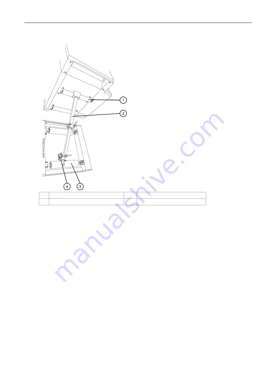
Figure 84 Aligning the unwinder with the ILP feed stepping plate assembly
1
Unwinder exit upper roller
3
Stepping plate roller
2
Parallel jig
4
Parallel jig dial bracket
9.
To align the unwinder with the ILP feed stepping plate assembly (Figure 84):
a.
Adjust the length of the Parallel jig to measure the variation in distance between the
unwinder exit upper roller and the stepping plate roller shown in Figure 84.
Mount the Parallel jig between the two rollers.
b.
Move the Parallel jig from front to back to accurately align the unwinder exit upper
roller (Figure 84).
Make sure that the rollers are aligned to an accuracy of 0.00
±
0.01 mm.
If
necessary:
i.
Remove the Parallel jig.
ii.
Loosen the unwinder exit panel securing screws.
iii.
Slightly move the panel.
iv.
Retighten the panel securing screws.
v.
Re-level the unwinder exit upper roller using the level.
vi.
Re-align the unwinder with the ILP stepping plate assembly.


