Installation Manual
CA294-03070 rev 00
page 108 of 153
Connect the air supply
NOTE:
All air supply hoses are to be routed appropriately under the
floor platform.
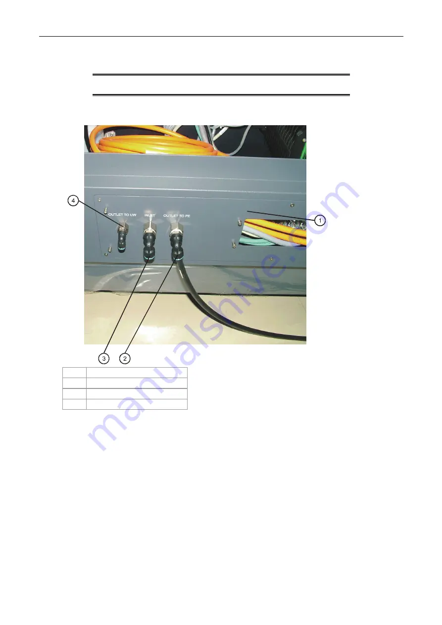
Figure 88 Connection the air supply at the ILP
1 ILP
front
2
Air outlet to PE connection
3
Air Input connection
4
Air outlet to unwinder
At the ILP front
1.
Connect the following air hoses at the ILP front:
a.
Input hose from mains air supply to
Inlet
connection.
b.
Long outlet hose from
Outlet to PE
connection to PE1.
c.
Long outlet hose from
Outlet to UW
connection to the unwinder.


