Installation Manual
CA294-03070 rev 00
page 109 of 153
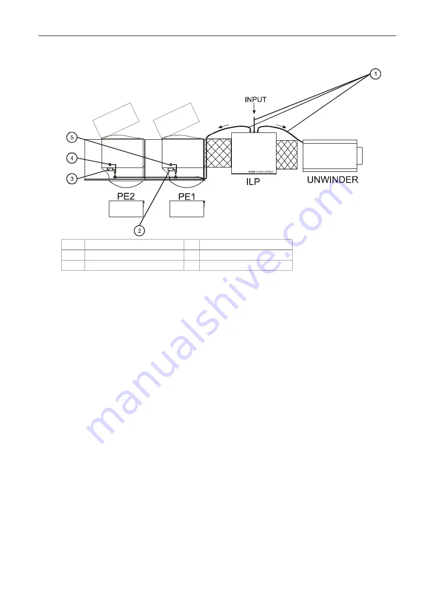
Figure 89 Routing the air hose from the ILP
1
Air hoses
4
PE2 ILD air pressure dial
2
PE1 air manifold
5
PE1 ILD air pressure dial
3
PE2 air manifold
2.
Route the Outlet to the PE1 air supply manifold as follows (Figure 89):
Around the back of the ILP
Under the PE1 to the front of the engine air manifold


