Installation Manual
CA294-03070 rev 00
page 110 of 153
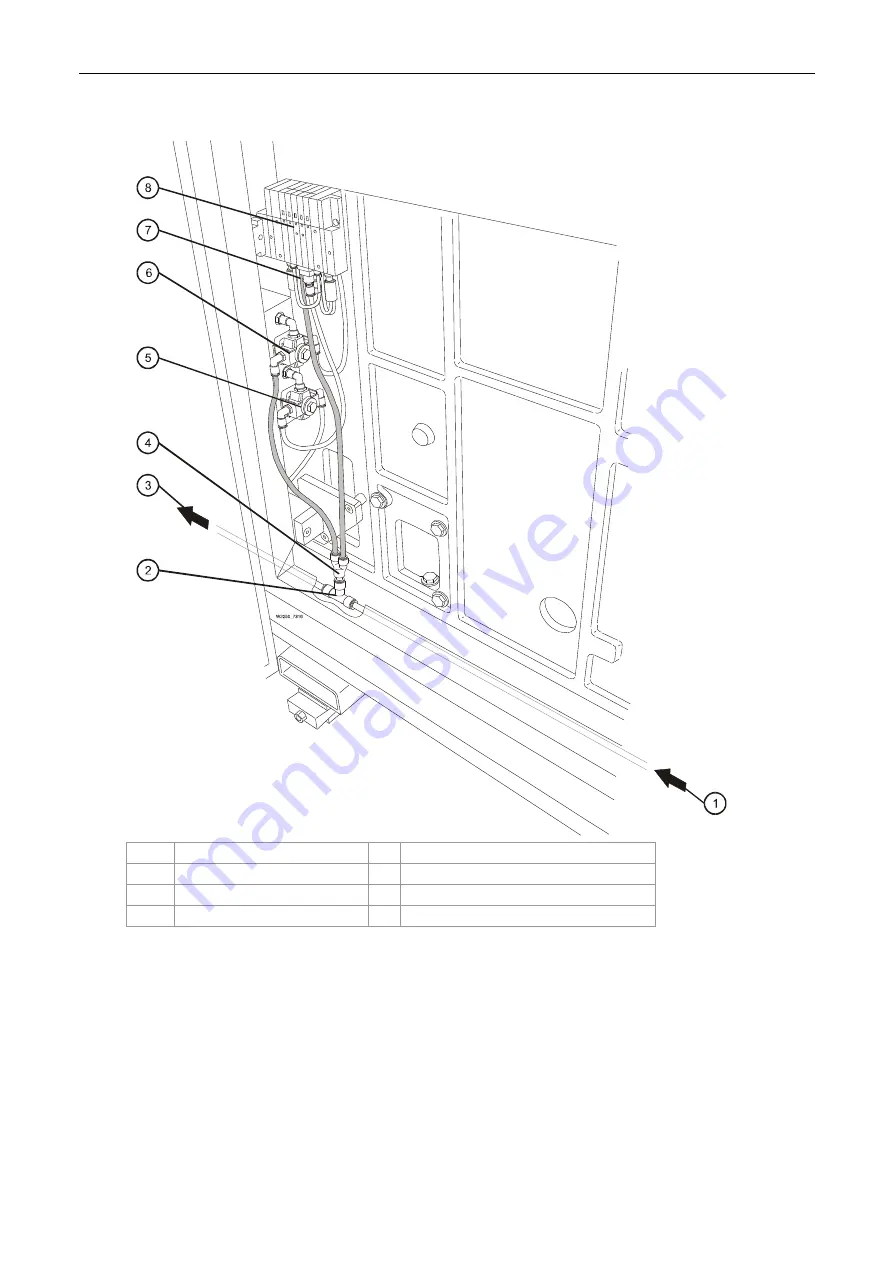
Figure 90 Routing and connecting the air hoses at PE1 and PE2
1
Air input from ILP
5
Web guide air pressure dial
2
T-junction
6
ILD air pressure dial
3
Air output to PE2
7
Web guide air input connection
4
V-junction adapter
8
Air manifold
At the PE1 air manifold
3.
Install the hose to the PE1 air manifold (Figure 90):
a.
Fit a T-junction to the end of the hose.
b.
Fit a v-junction adapter in the top outlet of the T-junction.


