Installation Manual
CA294-03070 rev 00
page 114 of 153
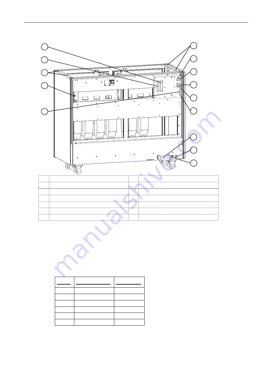
Figure 95 The ink cabinet – rear view
IN OUT
7
8
9
6
5
4
3
2
11
1
12
10
1
13
1
Screws for securing the working surface
8
Cooling water OUTPUT
2
J21 - not in use
9
Cooling water INPUT
3 J20
10
J24
4
J22
11 Imaging oil add
5
J23
12 J31 - Not in Use
6 Grounding
cable
13
J30
7 Guard
bracket
Install each ink cabinet as follows:
1.
Fill the ink tanks with imaging oil and install the ink pumps.
2.
Install the ink tank assemblies in the ink cabinet.
3.
Install the ink cans in the proper order (Figure 93 and Figure 94).
4.
Fill the imaging oil reservoir with imaging oil.
5.
Connect the following cables between the printing engine and the ink cabinet (Figure 95):
Cable
Printing engine
Ink cabinet
W2 P20
J20
W27 P22
J22
W8 P24
J24
P23
(W29) J23
W49
J30
W20
J2


