Installation Manual
CA294-03070 rev 00
page 118 of 153
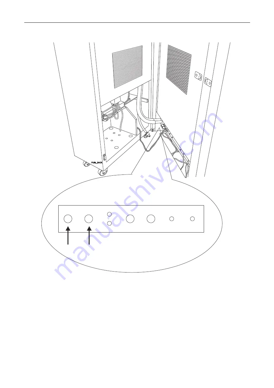
Figure 99 Connecting the utility cabinet to the printing engine
OUTLET
INLET
IN
OUT
SOLID ADD
COMP AIR
POWER
CABLE
CONTROL
CABLE
OUTLET
HOSE
INLET
HOSE
3.
Connect the following hoses from the utility cabinet to the printing engine (Figure 99):
•
Cooling water in
•
Cooling water out
•
Solid add compressed air
•
Impression drum cooling drain
•
Vacuum
•
Air
flow
4.
Connect the control cable and power cable to the utility cabinet (Figure 99).


