Installation Manual
CA294-03070 rev 00
page 22 of 153
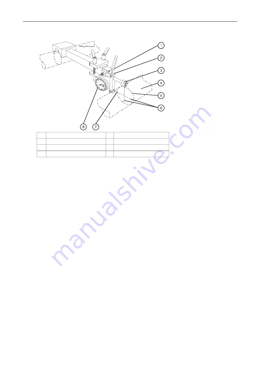
Figure 6 Mounting the dial bracket on the extension
1
Dial bracket securing screw 5
Positioning
circle
2
Dial bracket
6
Center lines of roller
3
Buffer
7
Position of dial sensor tip
4 Roller
8 Dial
4.
Mount the gauged end of the jig on the specified roller needing to be aligned.
5.
Loosen the screw securing the gauge support on the fixture, and slide it back so it does not
interfere with placing the wheel.
6.
Loosen the lock nut for the handle securing the gauge fixture in the extension.
7.
Adjust the position of the gauge fixture in the extension so that the wheel rests on the roller
and coincides with the vertical centerline of the roller.
Tighten the handle and the lock nut.
8.
Slide the gauge support back until the contact touches the roller.
Continue sliding the gauge until the needle makes one complete turn.
Tighten the screw to secure the gauge support in place.
Prerequisites
Completion of site preparation.
Estimated installation time
4 days
Special skills
Only specially trained personnel should perform this installation.
Special jigs and tools
All special jigs and tools required for the installation of the press are included in the installation kit.
Confirm the contents of the installation kit with the Bill of Materials (BOM).


