Installation Manual
CA294-03070 rev 00
page 37 of 153
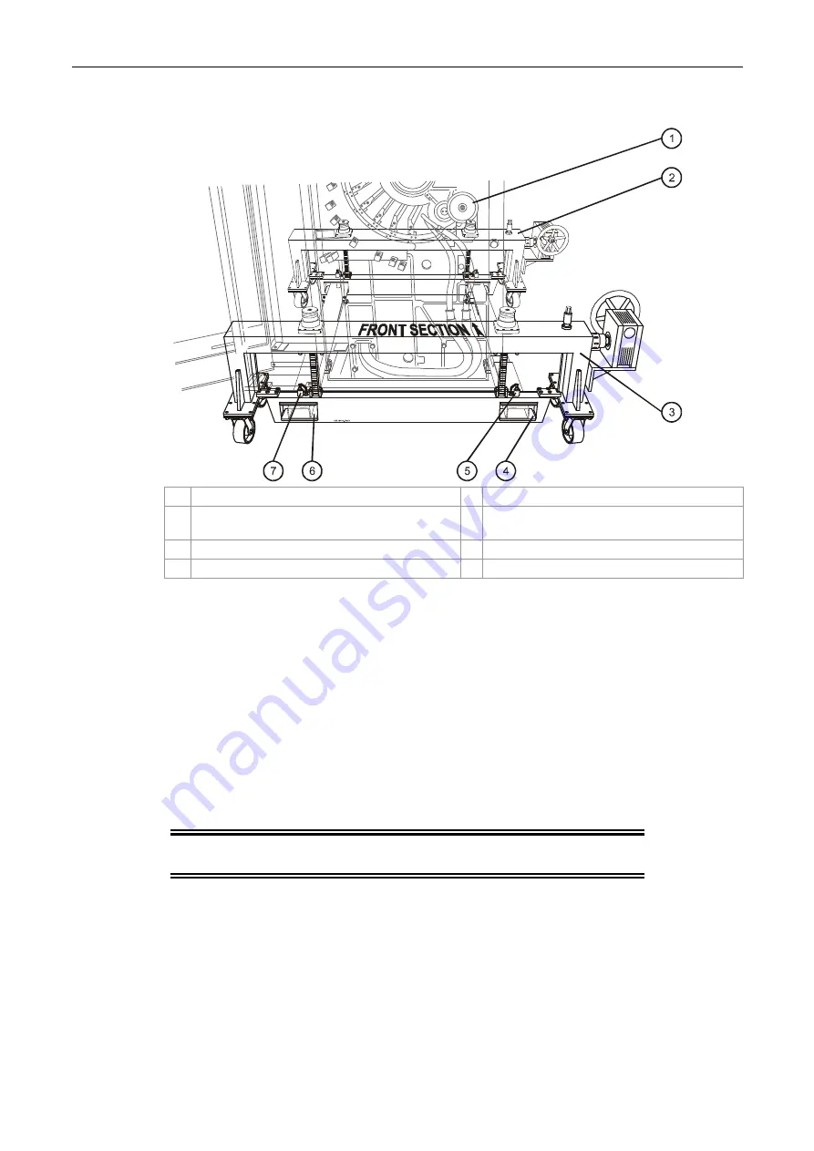
Figure 20 Positioning the lifting frames against the engine
1
Engine frame
5 Metal securing peg
2
Rear lifting frame
6 Lifting frame slot securing end of exit link
bar.
3
Front lifting frame
7 Metal securing peg
4
Lifting frame slot securing end of feed link bar
g.
Position the front and rear lifting frames against the engine so that the feed and exit
link bars are inserted in the lifting frame slots (Figure 20).
h.
Make sure that the link bars are inserted sufficiently to the lifting frame slots so that
metal securing pegs can be fully inserted to the holes between the link bars and the
lifting frames.
i.
Insert the metal securing pegs to the holes between the link bars and the lifting
frames.
j.
Turn each wheel jack (Figure 17) at the four corners of the lifting frames an equal
number of turns, in steps of 3-4 turns, to raise the engine 20 cm.
This will allow mounting of the engine on the u-base (Figure 17).
CAUTION:
Do not tilt the press, as this could cause the press
to fall and become damaged.


