Installation Manual
CA294-03070 rev 00
page 40 of 153
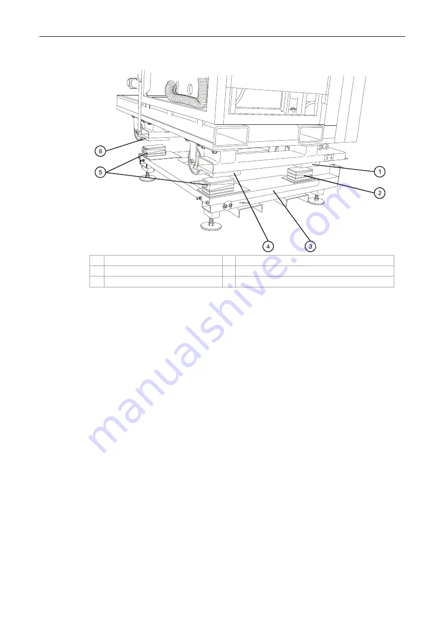
Figure 24 Press positioned over u-base
1
Feed base frame underside slot
4
Feed base frame underside slot
2
Leveling pad
5
Leveling pads
3 U-base
6
Exit base frame underside slot
m.
Carefully move the lifting jig and press over the u-base until the feed and exit base
frame underside slots (Figure 30) are aligned correctly with the top surfaces of the
leveling pads (Figure 23 and Figure 24).
If necessary, move the u-base to correctly align the underside slots with the leveling
pads top surfaces.


