Installation Manual
CA294-03070 rev 00
page 48 of 153
parallel jig to bring the centerlines of the printing engines into
parallel.
Both adjustments are then checked and repeated, if
necessary, until the centerlines of the printing engines are
collinear.
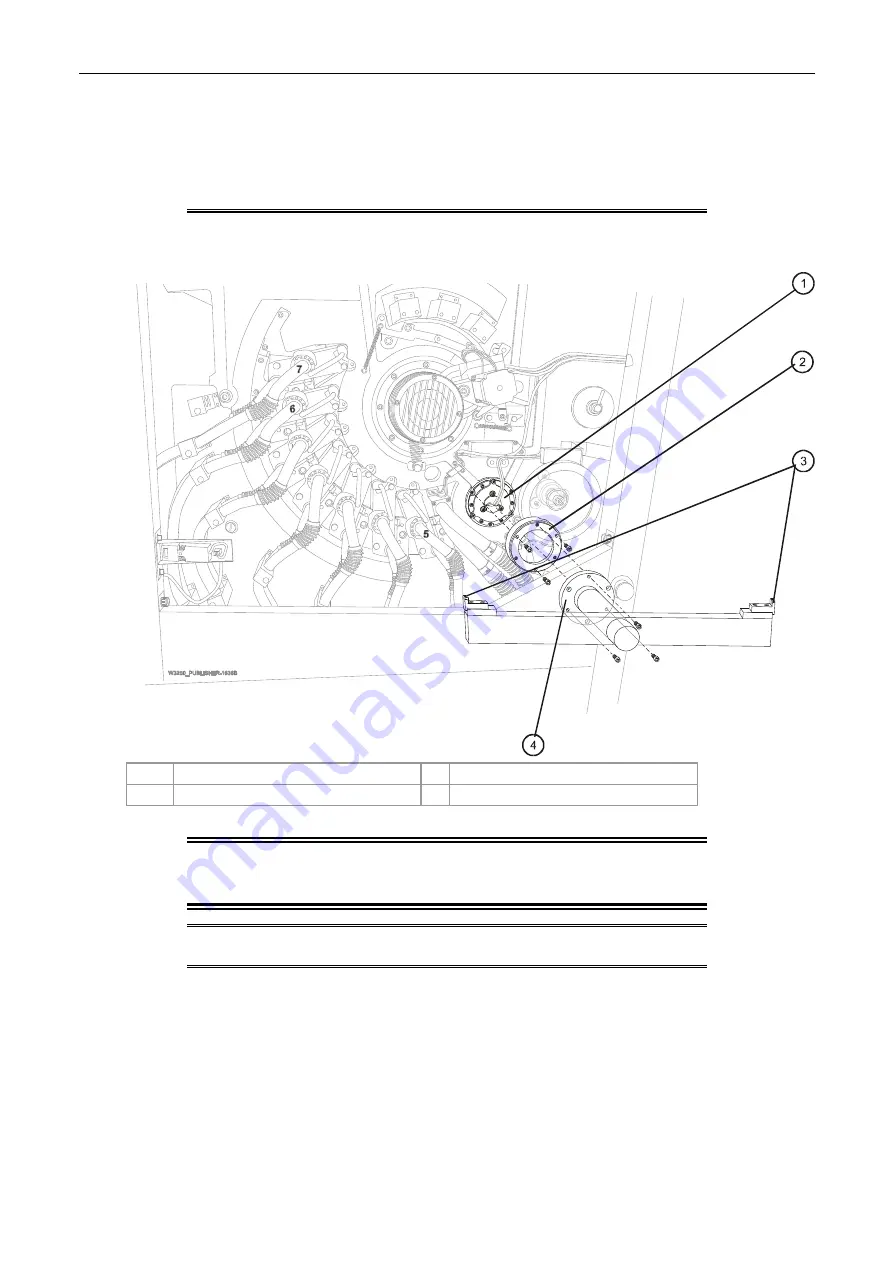
Figure 32 Mounting an alignment jig on the ITM end cap
1
ITM bearing housing plate
3
Sights
2
Alignment jig adapter
4
Alignment jig mounted on ITM end cap
CAUTION:
When installing the alignment jigs, make sure not
to damage the ITM lamp or any wires exiting from
the lamp.
NOTE:
General information on page 17 for details on mounting
and using the jigs.


