Installation Manual
CA294-03070 rev 00
page 51 of 153
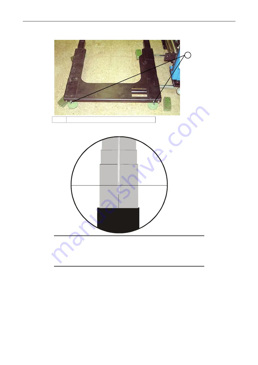
Figure 34 Identifying the u-base adjustment screws
1
1
Inner screws - for aligning the PE accurately
Figure 35 Aligning the surveying tool crosshairs and sights
NOTE:
When adjusting the u-base slip plates, tightening the inner
screws moves the printing engine towards the rear and
loosening them moves it towards the front.
Each turn of the u-base slip plate inner screws moves the
printing engine by 0.3 mm.
e.
Adjust the inner screws on the u-base slip plate of each printing engine until the
sights on both alignment jigs are aligned with the crosshairs in the surveying tool
(Figure 33 - Figure 35).
They should be aligned such that the crosshairs of the surveying tool are located at
the center of the four sights.
f.
Adjust the printing engines until each one is aligned to ±0.1 mm.


