Installation Manual
CA294-03070 rev 00
page 79 of 153
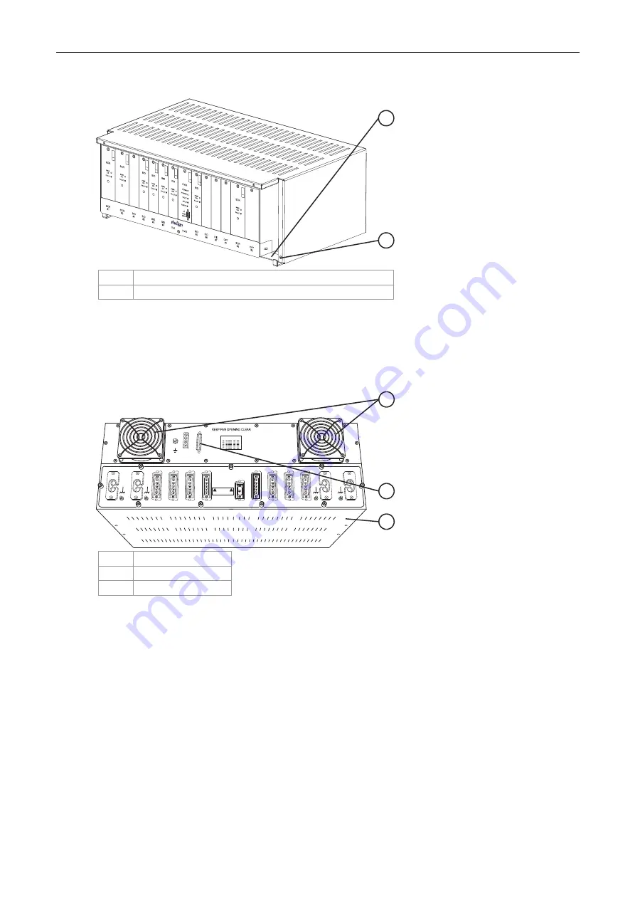
Figure 61 Attaching the top cover to the baseplate
HVP
SCA
GE1
.CD
R
2
1
1 Baseplate
2
Screws securing top cover to baseplate (4 places)
4.
Use four MBG 4
×
10 conic screws to attach the top cover to the baseplate (Figure 61).
5.
Install the HVPS front cover.
Figure 62 Connecting the cables to the HVPS
DANGER
HIGH VOLTAGE
WARNING
HVPSFANS.CDR
OPT#2
SCR#3
GND
24VDC
J3
J2
HVPS
I/F
OPT#1
BID#7
BID#6
BID#5
BID#4
BID#3
BID#2
BID#1
SCR#2
SCR#1
ITM
2
3
1
1 Fans
2 J2
connector
3 Cage
6.
Connect the cables to the HVPS (Figure 62).
7.
Install the HVPS rear cover.
Install the roof covers
Install the two roof covers above and opposite the writing head.


