Installation Manual
CA294-03070 rev 00
page 102 of 153
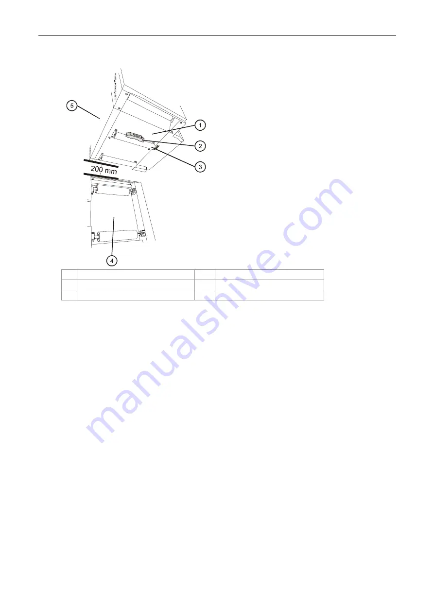
Figure 83 Checking the level at the unwinder exit
1
Unwinder exit panel
4
ILP feed stepping plate assembly
2 Leveler
5 Unwinder
3
Unwinder exit upper roller
At the unwinder exit
6.
Secure the two unwinder exit rollers by tighten the screws securing the unwinder exit panel
(Figure 83).
7.
Check the level at the unwinder exit upper roller shown in Figure 83.
If necessary, readjust the height of the leveling pads until the unwinder is level at all positions.
If necessary, slightly loosen the unwinder exit panel screws and readjust the position of the
unwinder exit panel (Figure 83).
Tighten the unwinder exit panel screws to secure the panel.
8.
Verify that the unwinder is 200 mm from the ILP feed stepping plate assembly (Figure 83).
9.
Reconfigure the parallel jig for the long configuration. Refer to the section General information
on page 17.


