Installation Manual
CA294-03070 rev 00
page 105 of 153
3.
Connect the interface cable (P/N GW Art. NR.8110.00361) to X4 in the unwinder
electronics compartment.
Connect the other end to JX66 in electrical cabinet M1.
ILP electrical connections
1.
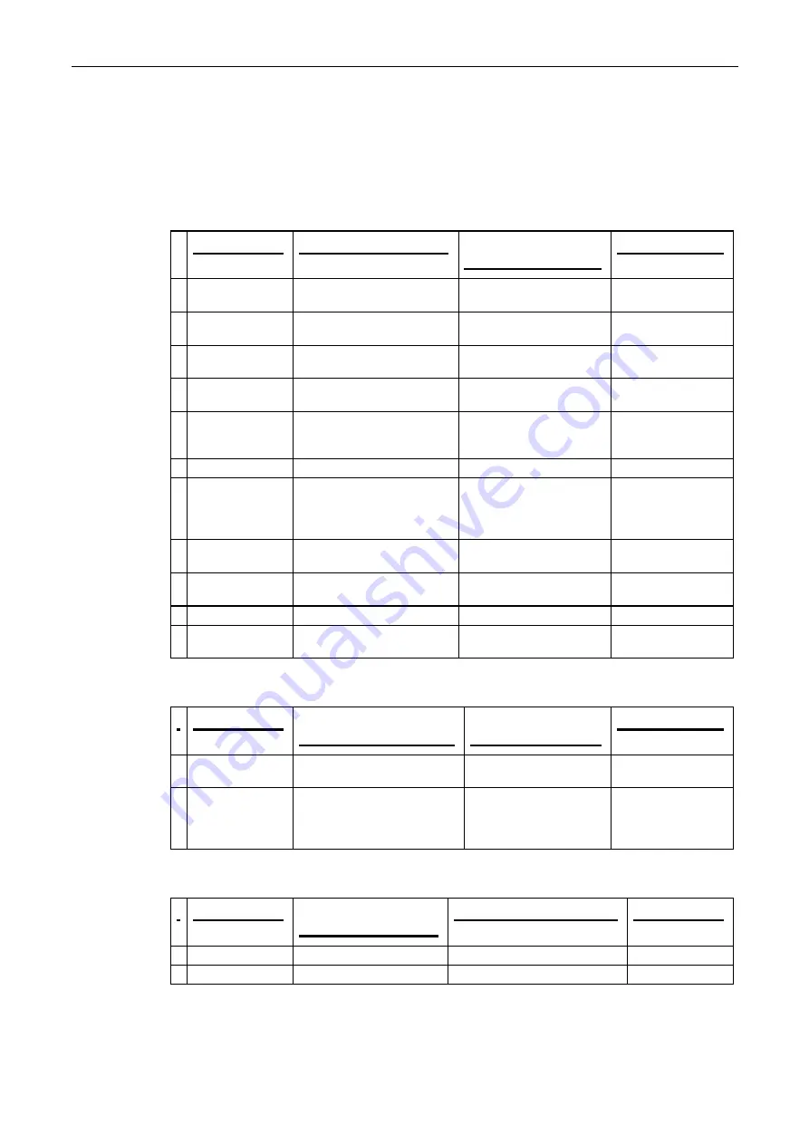
Install the following cables between the ILP connections panel and cabinet M1:
Cable
Origination point ILP
End point
cabinet M1
Notes
CA293-09160
Orange
FU Motor connection
Connection
JX26
CA293-09170
Green
FU Motor encoder
FU UniDrive (Motor
encoder FU) at
26U0
CA293-09190
Green
FB Motor encoder
U/W UniDrive (Motor
encoder FB) at
24U0
CA293-09180
Orange
FB Motor connection
Connection
JX24
CA261-10240
ILP control cable
X60
at
ILP JMB board
(ILP connection panel)
Connection
X60
CA261-10890
ILP/JX70
interlock cable
Connection at
JX70
CA261-10590
MPI bus to ILP TSP
(ILP connection panel)
MPI connection at PLC
53A1
Route the cable
from the ILP, under
the floor to the PE1
and PE2 exits
CA261-11040
ILP priming motor power at
JX22
Connection at
JX22
Cable labeled
1-46-05
CA261-10880
ILP Ametek power at
JX43
Connection
at
JX43
and
DA-J2
Cable labeled
1-46-05
CA261-09210
ILP Ametek control at
JX2
Connection
at
JX2
CA261-10900
ILP 24 VDC at
JX57
Also, connection at
JX59
Connection at
JX57
2.
Install the following cables between cabinet M1and the ILP connections panel :
Cable
Origination point
cabinet M1
End point
ILP
Notes
CA261-10620
ProfiBus
ILP Profibus to I/O plate (ILP
connection panel) at
16I/O
ILP platform at
connection at
53A1
CA261-10870
Green/yellow
Grounding cable
Grounding cable connection
at inner ILP
Grounding cable
Grounding connection
at Grounding bracket in
cabinet M1
3.
Connect the following air hoses and cables to the ILP connections panel:
Cable
end point
ILP
Origination point
Notes
CA261-10710
Inlet hose to Water tank
Water pump at ILP
Outlet hose to PE1
ILP compressor pump.


