Installation Manual
CA294-03070 rev 00
page 106 of 153
Cable
end point
ILP
Origination point
Notes
Inlet hose from air valve
at wall.
Main compressor pump outlet.
Outlet hose to unwinder
ILP compressor pump.
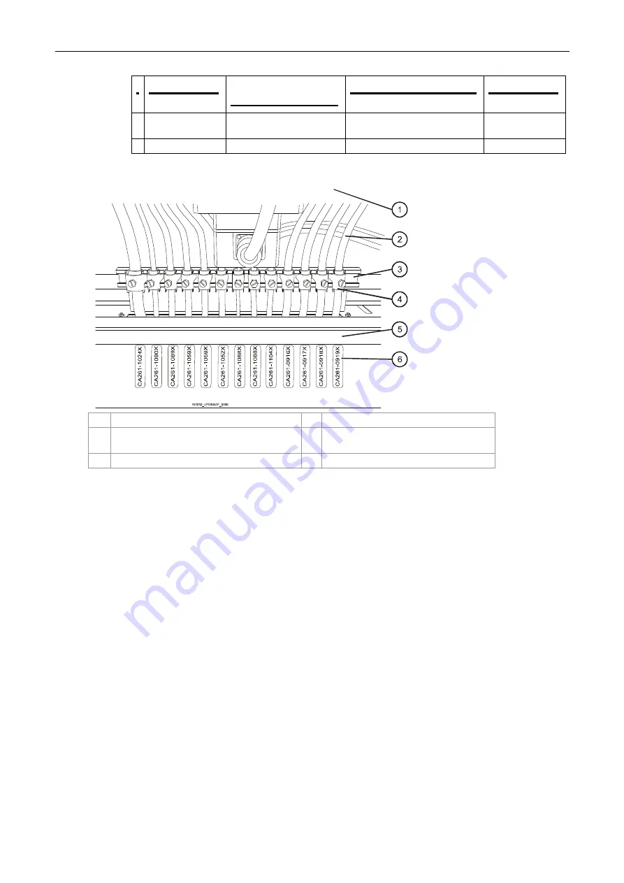
Figure 86 Install cable securing clamps at the ILP
1
Rear inner ILP
4
Securing clamps
2
Cables from ILP assemblies to cabinet M1
and PE1
5
ILP rear panel
3
Clamp rail
6
Cable labels
4.
Install the cable securing clamps on the clamp rail as shown in Figure 86:
a.
Arrange the cables according to the cable securing panel labels shown in Figure 86.
b.
Mount securing clamps on each cable to secure the cable in position.


