Installation Manual
CA294-03070 rev 00
page 115 of 153
6.
Remove the outer screw securing the guard bracket, and turn the bracket counterclockwise to
expose the cooling water connections (Figure 95).
7.
Connect the two cooling water hoses to the ink cabinet (Figure 95).
8.
Connect the black plastic imaging oil tube to the ink cabinet (Figure 95).
9.
Connect the solid add compressed air tube to the ink cabinet (Figure 95).
10.
Remove the front cross panel above the ink cabinet.
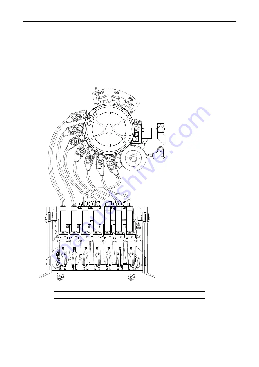
Figure 96 Mapping the BID hoses from the ink cabinet to the BIDs
C
K
M
5t
h
Y
6th
7t
h
NOTE:
The BID hoses are labeled.


