Installation Manual
CA294-03070 rev 00
page 38 of 153
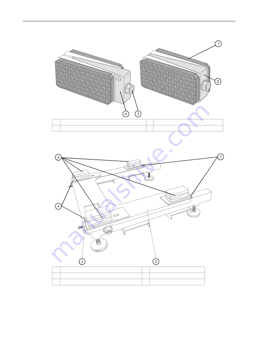
Figure 21 Leveling pad
1
Pad
3 Allen M10 screw
2
Default height adjustment wedge position
4
Height adjustment wedge
Figure 22 Placing the leveling pads on the u-base
1
Leveling pad slots
4
Leveling pad slots
2 U-base
cover
5
Leveling pads
3
Allen M10 height adjustment screw
6
k.
Mount four leveling pads (Figure 21) at the four corner slots of the u-base (Figure 22).
Make sure that the pads are mounted centrally on the slotted areas of the u-base
cover as shown in Figure 22.


