Installation Manual
CA294-03070 rev 00
page 56 of 153
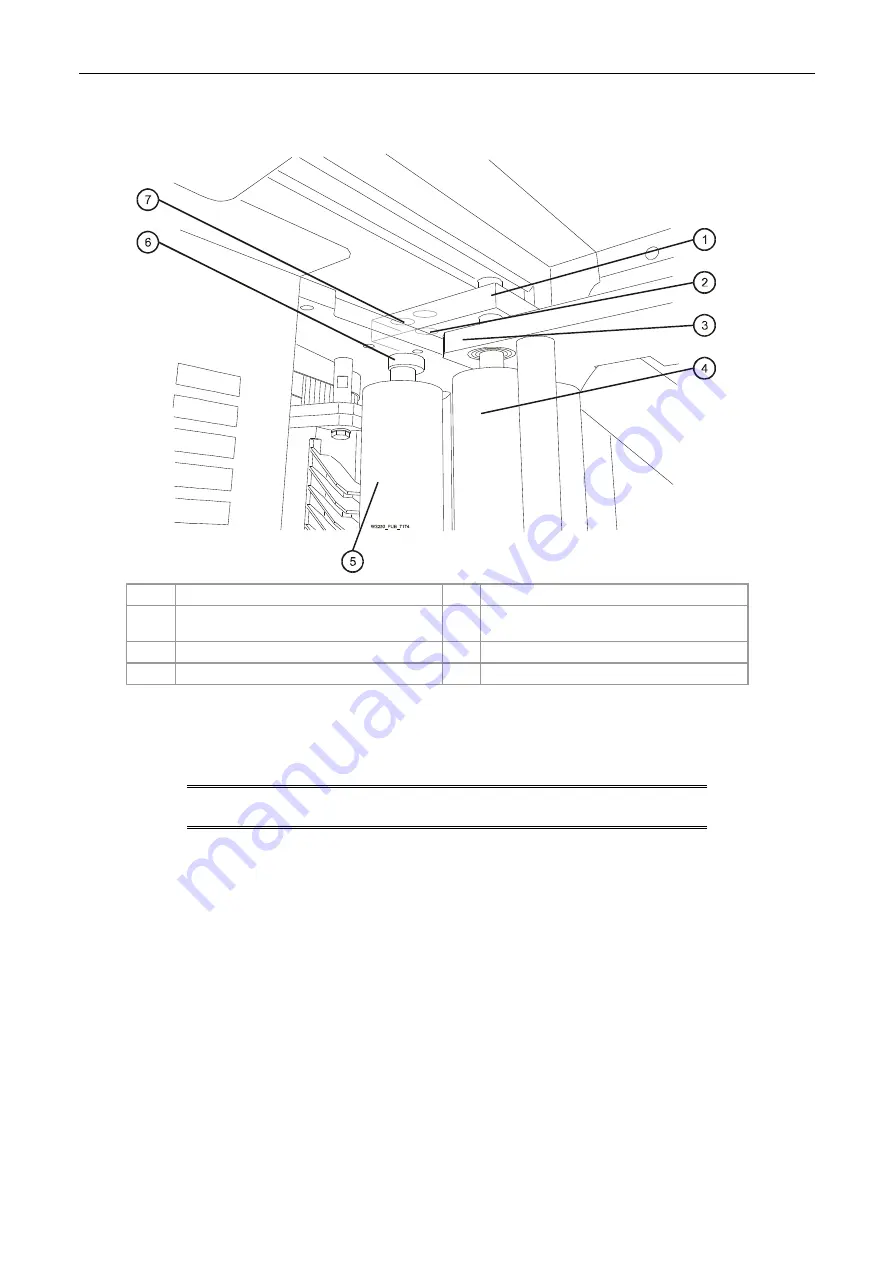
Figure 41 Securing the rear connection bracket and input idler
1
Rear connection bracket
5
PE2 input idler
2
Lower screw securing the rear connection
bracket
6 Collar
spacer
3
Turnbar rear wall
7
Upper screw securing the idler
4
Turnbar input idler
5.
Install the rear collar spacer (Figure 41).
6.
Install two additional Allen M5 screw (P/N MBS-0840-10) to secure the rear connection
bracket (Figure 41).
NOTE:
Before tightening all the screws to secure the turnbar, make
sure that all of the turnbar rollers move without friction.
7.
Holding the turnbar in position, tighten the screws.
8.
Connect the turnbar air hose to the turnbar air pressure air valve.
9.
To connect the printing engines to each other:
a.
Mount the front link bracket (Figure 37 and Figure 38).
Install the two 19 mm bolts and the two M6 Allen screws.
Do not tighten the joining M10 Allen screw yet. It remains loose for final adjustments.
b. Repeat
a above for the rear link bracket (Figure 37).
c.
Check the horizontal alignment of the printing engines using the surveying tool.
Realign, if necessary.


