Installation Manual
CA294-03070 rev 00
page 69 of 153
Figure 49 Routing the MPI (MODBUS) cable
TBD
12.
Route the MPI (MODBUS) cables as follows (Figure 49):
a.
Route the ILP connection panel section to the electrical cabinets.
The raised floor should be installed before connecting to the ILP.
b.
Route it to the front of PE1 and along bottom of the frame to the turnbar area.
c.
Connect JTBD of the cable to PTBD of the TBD.
d.
Route the remaining connector JTBD to the exit are of PE2.
Connect it to PTBD of the TBD.
13.
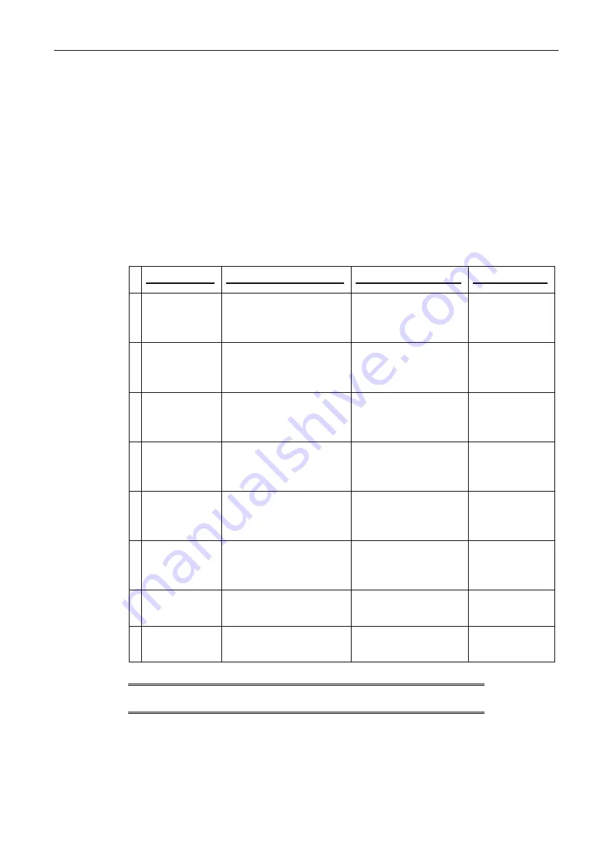
Connect the ProfiBus and CTNet cable connections at electrical cabinets M1 and M2 as
follows:
Cable
Origin point
End point
Notes
CA294-11200
CC428
Purple
Profibus
Cabinet M2
80A7
connection
Cabinet M1
53A5
connection
Purple cable terminator
should be turned off.
Connection is on
top of cable
11190.
CA294-11200
CC428
Purple
Profibus
Cabinet M2 PLC connection
60A2
Cabinet M1
53A5
connection
Verify connection
CA294-11200
CC428
Purple
Profibus
Cabinet M2 PLC connection
80A2
Cabinet M1
53A5
connection
Verify connection
CA294-11200
CC428
Purple
Profibus
Cabinet M2 PLC connection
U3/VB2
Cabinet M1
53A5
connection
Verify connection
CA294-11200
CC428
Purple
Profibus
Cabinet M2 PLC connection
U5/VBX
Cabinet M1
53A5
connection
Verify connection
CA294-11200
CC428
Purple
Profibus
Cabinet M2 PLC connection
60A7
Cabinet M1
53A5
connection
Verify connection
CTNet
10960
Green
CTNET cable connection
JX57
at M1
Connection at Unidrives
CTNet
Green
09190
Unidrive
24U0
FB encoder
5-pin connection at
UD75
in
Cabinet M1
Cabinet M2
U029
turn
bar feed (FX) controllers
5-pin connection at UD75
NOTE:
All electrical cables will be routed under the floor platform as
necessary.


