Installation Manual
CA294-03070 rev 00
page 72 of 153
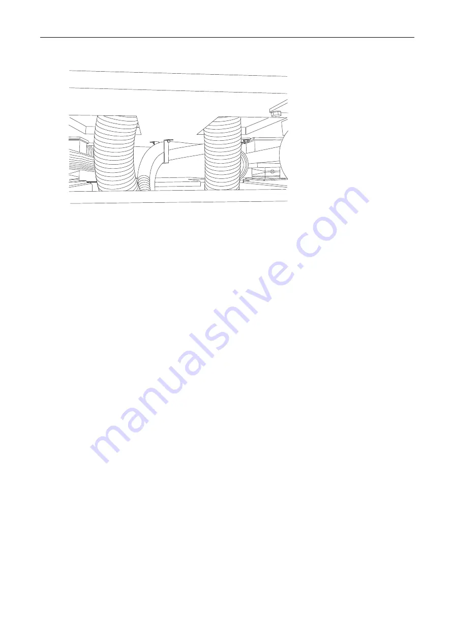
Figure 52 Routing vacuum hoses to PE2
PUB_6868
4.
Route the short ~2m hose connected to the left blower in electrical cabinet M2 to the vacuum
box in PE2 (Figure 50 and Figure 52).
Use adaptors and small hoses as shown to connect to the vacuum box.
5.
Route the short ~2m hose connected to the right blower in electrical cabinet M2 to the
vacuum box in PE2 (Figure 50 and Figure 52).
Use adaptors and small hoses as shown to connect to the vacuum box.
6.
Reinstall the underside covers to each printing engine.
7.
Route the long 3 – 4 m vacuum hose to the ILP. Refer to the section Installing the ILP on
page 81 for details of the connection to the ILP.
Install the floor platform
At this point in the installation of the press, the customer should have the floor platform installed. The
floor platform must meet the specifications detailed in the HP Indigo press w3250 site preparation
guide.
The customer engineer should inform the floor platform installers to start installing the floor at the
unwinder and ILP positions.
When installing the floor near the press, the installation should either be started at the corners of the
press or at the wall, depending on the convenience of the installation engineer.
Installing the chiller and cooling water hoses
The press uses cold water to control its environment temperature as well as the temperatures of other
systems such as ink tanks and imaging oil. The chiller supplies the cold water to the press.
The chiller is connected to an accumulation tank with two water pipes (inlet and outlet) and a control
cable. The accumulation tank supplies each printing engine with cooling water via a pump.
Cooling water supplied to the press must meet the following conditions:
•
Flow rate of 56
±
5 liters/minute
•
Temperature (measured at the press inlet) of 6
°
C


