Installation Manual
CA294-03070 rev 00
page 76 of 153
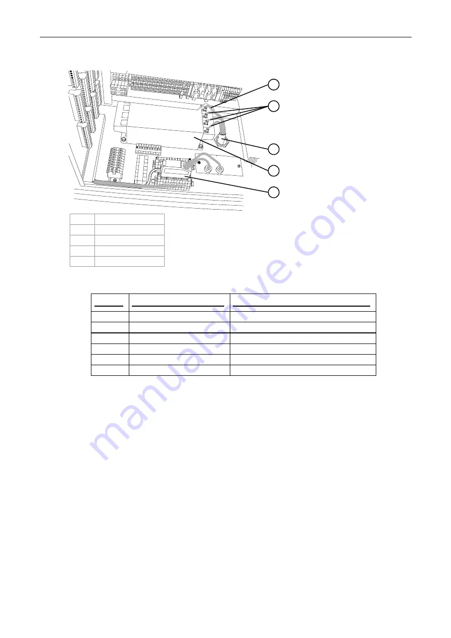
Figure 56 Connecting the UPS to the PDU
PDU_CONN1
3
4
5
2
1
1 Neutral
2 Three
phases
3 Main
4 Breaker
button
5
Input from PC
1.
Install and connect the UPS cables as follows:
Cable
From end point
To end point
CC73A
UPS No. 1 from slave 1 PC
RS232 COM (SNMP) port at the 1
st
UPS
CC74A
UPS No. 2 from slave 2 PC
RS232 COM (SNMP) port at the 2
nd
UPS
CC77A
UPS cable from master PC
RS232 COM (SNMP) port at the 3
rd
UPS
CC233
Output cable from slave 1 PC
Input connection at the 1
st
UPS
CC234
Output cable from slave 2 PC
Input connection at the 2
nd
UPS
CC235
Output cable from master PC
Input connection at the 3
rd
UPS
2.
Make sure that the cables are connected between the UPSs, the PEs, and the electrical
cabinets.
Install the writing head
1.
Carefully remove the writing head (P/N CA270-00101) from Box No. 8.
2.
Remove the parameters diskette from the top of the writing head and save the diskette for
later use.
3.
Remove the four screws securing the plate secured to the heater window at the underside of
the writing head.
Remove the plate. Save the plate in case of writing head replacement.
4.
Install the writing head above the scorotron bridge. Refer to the service documentation
Writing Head
for further details.


