Installation Manual
CA294-03070 rev 00
page 84 of 153
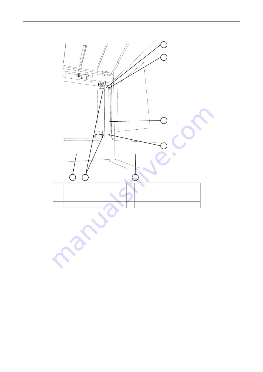
Figure 66 Installing the stepping plates to the ILP
W
3250_S
TE
P
_P
LA
TE
_4084
ILP EXIT
EXIT STEPPING
PLATE ASSEMBLY
4
5
3
2
1
6
7
1 Lower
bracket
5
ILP
2
Upper securing screw
6
Lower securing screws
3
Upper frame
7
Stepping plate assembly
4
Upper securing screw
c.
Install the exit stepping plate assembly to the ILP using four Allen M5 screws,
washers, and spring washers (Figure 66).
Two screws are inserted at the upper frame and two within the lower bracket slots.


