EN
Overview 3
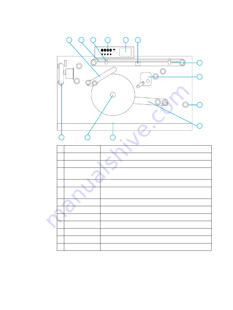
Figure 1-1 shows the main components of the rewinder.
Figure 1-1. Rewinder components
1
Riding roller
Prevents wrinkles and electrostatic build-up in the final roll.
2
Splicing table
Used for splicing the web.
3
Left clamp
Holds the substrate in place for splicing.
4
Tension control panel Controls the tension in the rewinder (see "Using the tension control
5
Touch screen
Operates the rewinder (see "Using the touch screen" on page 5).
6
Anti-vacuum roller
Prevents vacuum build-up between the moving web and the splicing
table.
7
Right clamp
Holds the substrate in place for splicing.
8
Nip cassette
Creates tension in the web before it is rolled on the rewinder spindle.
9
Alignment roller
Used for aligning the printing engine and the rewinder.
10 Dancer arm
Keeps the web taut between the printing engine and the rewinder.
11 Ultrasonic sensor
Stops the rewinder when the final roll reaches the maximum size.
12 Rewinder spindle
Removes substrate.
13 Web guide
Compensates for lateral web movement.
12
1
2
3
5
6
13
11
7
8
9
10
4


