background image

Remove or replace a 1.8-inch SSD option drive

About this task

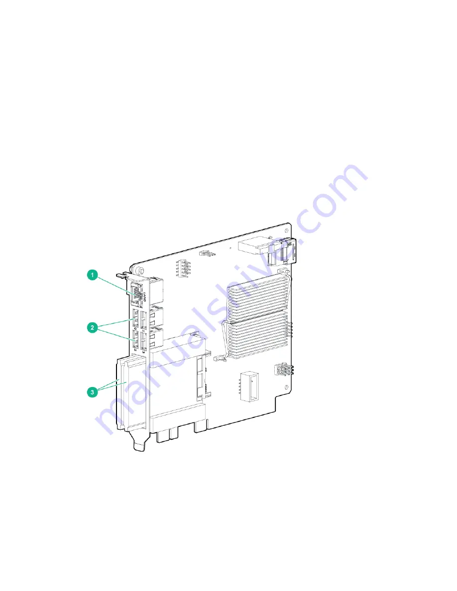
The BaseIO card supports two optional “mini” 1.8-inch SATA solid-state-drives (SSDs) which are
accessible from the front of the chassis. The two SSD slots are located directly below the BaseIO board’s
USB ports. The two SSDs connect internally via a cable to two 6GB/s SATA ports. The SSDs are
accessible from the front of the chassis. A metal cover used to protect the SSDs is held in place by a
single T10 Torx screw. An SSD may be hot-swapped only if it is part of a RAID drive-pair. In this case you
may leave the operating system running and the MC990 X server chassis in the rack.

Use the following information to remove or replace a 1.8-inch SSD in the BaseIO:

Procedure

1.

Access the front of the rack and remove the MC990 X server chassis front panel (bezel) by grasping at
either end and pulling it off.

2.

Use a T10 Torx driver to unscrew and remove the outer metal cover that protects the SSDs.

3.

Extract a drive by grasping the front of the drive and pulling straight out.

4.

Insert a new drive by sliding the SSD into the empty slot until it fully engages the connector.

5.

Replace the BaseIO board SSD cover and secure it with the T10 Torx screw.

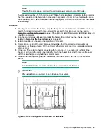
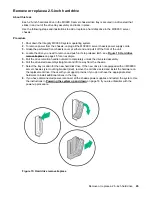
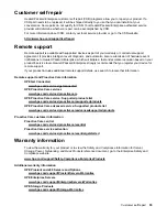
Figure 16: Optional 1.8-inch solid state drives

46

 Remove or replace a 1.8-inch SSD option drive

Summary of Contents for Integrity MC990 X

Page 1: ...hitecture general operation and descriptions of the major components that comprise the HPE Integrity MC990 X Server system It also provides the standard procedures for powering on and powering off the system basic troubleshooting and maintenance information Foundation Software usage information and important safety and regulatory specifications ...

Page 2: ...owering the system up and down 16 Preparing to power up 16 Powering up and down from the command line interface 17 Booting directly from an RMC 17 Remote LAN connection to the RMC 18 Establishing RMC IP hardware connections 18 Power up the system using the RMC network connection 19 Monitoring power up 20 Power down the system 21 System control 22 Levels of system control 22 System management overv...

Page 3: ...drive 46 Replacing an MC990 X server chassis power supply 47 Replacing an MC990 X server chassis fan assembly 48 Integrity MC990 X system Troubleshooting 50 Troubleshooting chart 50 LED status indicators 50 Power supply LEDs 51 System motherboard status LEDs 51 Websites 53 Support and other resources 54 Accessing Hewlett Packard Enterprise Support 54 Accessing updates 54 Customer self repair 55 Re...

Page 4: ...System architecture 65 ccNUMA architecture 66 Cache coherency 66 Non uniform memory access NUMA 67 Safety and regulatory information 68 Safety information 68 Regulatory information 69 Regulatory Model Numbers 69 Glossary 70 4 Contents ...

Page 5: ...d party websites take you outside the Hewlett Packard Enterprise website Hewlett Packard Enterprise has no control over and is not responsible for information outside the Hewlett Packard Enterprise website Acknowledgements Intel Xeon are trademarks of Intel Corporation in the in the U S and other countries Google is a registered trademarks of Google Inc Linux is a registered trademark of Linus Tor...

Page 6: ...s storage units MC990 X server chassis The basic enclosure within the Integrity MC990 X system is the MC990 X server chassis The MC990 X server chassis contains one four socket motherboard connected to support up to 28 NUMAlink ports each with a maximum bidirectional bandwidth communication rate of up to 7 47 GB sec Each MC990 X server chassis has ports that are brought out to external NUMAlink co...

Page 7: ...upplies one four processor compute memory board and other optional riser enabled drives and boards for the Integrity MC990 X system The base server chassis also has a BaseIO riser not present in the expansion server chassis MC990 X base server chassis front components shows the MC990 X server chassis front panel components 1 USB ports 4 2 ETH0 3 DVD drive 4 System drive assembly 5 RMC 6 MGMT 7 Ser...

Page 8: ...on server chassis does not require a drive assembly and can accommodate four additional PCIe cards Internal PCIe enabled slots The MC990 X enclosure and motherboard support the following types of PCIe option boards Four full height half length Gen3 x8 PCIe slots Four full height 10 5 inch length Gen3 x8 PCIe slots Four full height double wide 10 5 inch length Gen3 x16 PCIe slots NOTE The x16 PCIe ...

Page 9: ...hows the front components of the BaseIO board The SSD drives bottom are enclosed with a metal cover 1 Ethernet port 2 USB ports 4 3 Solid State Drives 2 Figure 4 BaseIO board front panel components RMC This 1U high rack management controller provides external LAN and USB connections into the Integrity MC990 X system and acts as a top layer of system control An internal 24 port Ethernet switch allo...

Page 10: ...mass storage may be added to the system along with additional MC990 X chassis You can add different types of PCIe board options to a server to achieve the desired system configuration You can easily configure systems around processing capability I O capability memory size or storage capacity Each air cooled MC990 X chassis has redundant hot swap fans and redundant hot swap power supplies Distribut...

Page 11: ...devices are distributed within the MC990 X server chassis Each BaseIO riser is accessible by all compute nodes within the SSI through the NUMAlink interconnect fabric Rack management controller Each Integrity MC990 X system has a rack management controller RMC located directly above or below the MC990 X server chassis in a rack The RMC supports powering up and down of the system motherboards and e...

Page 12: ...y devices 8 bits or more apart All high speed links including Intel Quick Path Interconnect QPI Intel Scalable Memory Interconnect SMI and PCIe have cyclic redundancy check CRC check and retry The NUMAlink interconnect network is protected by CRC Each MC990 X server chassis installed has status LEDs that indicate the server operational condition LEDs are viewable at the front of the unit Power on ...

Page 13: ...igh voltage areas Failure to follow these precautions will result in serious injury or death The high voltage areas of the system are indicated with high voltage warning labels CAUTION Power off the system only after the system software has been shut down in an orderly manner If you power off the system before you halt the operating system data may be corrupted System control network All MC990 X s...

Page 14: ...indicator Figure 7 RMC front panel connections Connecting to the system control network The Ethernet connection is the preferred method of accessing the system console Administrators can perform one of the following options for connectivity A portable system console can be directly connected to the RMC micro USB connect port labeled CNSL See Figure 7 RMC front panel connections on page 14 This req...

Page 15: ...owering up and down from the command line interface on page 17 for additional specific examples of using the CLI commands Example CLI commands used The following is a list of some available CLI commands auth authenticate SSN APPWT change bios perform bios actions bmc access BMC shell rmc access RMC shell config show system configuration console access system consoles help list available commands h...

Page 16: ...ll power plug receptacles are securely plugged in 2 For each individual MC990 X server chassis that you want to power up make sure that the power cables are plugged into all the chassis power supplies correctly see the example in Figure 8 MC990 X server chassis power supply cable location on page 16 Setting the circuit breakers on the PDUs to the On position will apply power to the individual MC99...

Page 17: ...s has information about its internal motherboard and options and also if other enclosures are attached via NUMAlink to the unit information about those MC990 X server chassis units Booting directly from an RMC Use a USB to micro USB cable to administer your system locally from the RMC Connect the cable from your administrative laptop or other device directly to the port labeled CNSL on the RMC Not...

Page 18: ...IP address To use the serial port connection you must attach and properly configure a micro USB interface cable to the RMC CNSL port Configure the serial port as described in USB connected console hardware requirements on page 17 When the serial port session is established the console will show an RMC login and the user can login to the RMC as user root Note that there is not by default a password...

Page 19: ...ing q Then reboot the RMC using the reboot command After reboot it will be configured with the specified IP address Power up the system using the RMC network connection About this task You can use a network connection to power on your Integrity MC990 X system as described in the following steps Procedure 1 You can use the IP address of the RMC to perform an SSH login as follows ssh root IP ADDRESS...

Page 20: ...ty mode enabled use CTRL q to exit uvcon console access established uvcon RMC BASEIO connection active START OF CACHED CONSOLE OUTPUT 20100512 143541 BMC r001i01b10 Cold Reset via NL broadcast reset 20100512 143541 BMC r001i01b07 Cold Reset via NL broadcast reset 20100512 143540 BMC r001i01b08 Cold Reset via NL broadcast reset 20100512 143540 BMC r001i01b12 Cold Reset via NL broadcast reset 201005...

Page 21: ...0 X system use the power off command as follows RMC power off r001i01c PRI You can also use the power status command to check the power status of your system RMC power status r001i01c PRI on 0 off 16 unknown 0 disabled 0 Power down the system 21 ...

Page 22: ...han its own configuration The Integrity MC990 X system control network also is not security hardened nor is it tolerant of heavy network traffic and is vulnerable to Denial of Service attacks System management overview An Ethernet connection directly from the RMC Figure 10 RMC front panel on page 23 to a local private or public LAN allows the system to be administered directly from a local or remo...

Page 23: ...the MC990 X server chassis in a rack The RMC slides out the front of the rack only The RMC uses an internal 24 port Ethernet switch which can provide system control for up to eight MC990 X server chassis in an expanded system The RMC accepts direction through IPMI 2 x enabled protocol software and supports powering up and powering down individual motherboards and environmental monitoring of all un...

Page 24: ...the MC990 X server chassis The individual motherboard BMCs do not have information on the status of other motherboards within the SSI This function is handled by the RMC and reported to an administrative console server Note that motherboards equipped with an optional BaseIO riser board have a dedicated BMC Ethernet port System controller interaction In all MC990 X server chassis the RMC and BMC sy...

Page 25: ...space Provides RJ45 ports for connections to the MC990 X server chassis BMC The following connectors and LEDs are also located on the front panel of the RMC Stack connector 38 circuit ipass connector used to expand the system management network by connecting to a second RMC WAN port RJ45 port used to connect to the customer s LAN or an in rack administration node AUX port RJ45 port currently is no...

Page 26: ...MEMlog utility has reported any hardware errors The MEMlog utility verifies and diagnoses problems with the DIMMs The utility s messages appear in var log messages Accessing MEMlog messages with commands on page 26 explains how to access information from the MEMlog utility through the monitoring tools or by using commands Accessing MEMlog messages with commands There are two ways to use commands t...

Page 27: ...idth 4 Rank 2 Row 15 Col 11 Bank 8 Serial 40C031C7 Part HMT31GR7EFR4C RD 1867 P2 DIMM1A Size 8192MB Width 4 Rank 2 Row 15 Col 11 Bank 8 Serial 402031AA Part HMT31GR7EFR4C RD 1867 P2 DIMM2A Size 8192MB Width 4 Rank 2 Row 15 Col 11 Bank 8 Serial 407031A8 Part HMT31GR7EFR4C RD 1867 P2 DIMM3A Size 8192MB Width 4 Rank 2 Row 15 Col 11 Bank 8 Serial 407031E7 Part HMT31GR7EFR4C RD 1867 P2 DIMM4A Size 8192...

Page 28: ...e gr_systat command monitors CPU and memory activity on x86 systems It s graphical output display includes information about CPU utilization I O wait times IRQs and memory utilization both for the system as a whole and for each node The gr_systat command is a useful performance monitoring tool nodeinfo command nodeinfo is a tool for monitoring per node NUMA memory statistics on MC990 X systems The...

Page 29: ...process running on another node that was full foreign Preferred node was full Had to allocate somewhere else interlv allocation was for interleaved policy local page allocated on THIS node by a process running on THIS node remote page allocated on THIS node by a process running on ANOTHER node press any key to exit from help screen topology command The topology command provides topology informatio...

Page 30: ...eed L1 KiB L2 KiB L3 KiB 0 r001i11b00h0 00 00 0 6 45 2599 32d 32i 256 20480 1 r001i11b00h0 00 01 2 6 45 2599 32d 32i 256 20480 2 r001i11b00h0 00 02 4 6 45 2599 32d 32i 256 20480 3 r001i11b00h0 00 03 6 6 45 2599 32d 32i 256 20480 4 r001i11b00h1 01 00 8 6 45 2599 32d 32i 256 20480 5 r001i11b00h1 01 01 10 6 45 2599 32d 32i 256 20480 6 r001i11b00h1 01 02 12 6 45 2599 32d 32i 256 20480 7 r001i11b00h1 0...

Page 31: ...06 03 00 0 186 1842 1872 Intel P3700 Non Volatile Memory Controller 14 r001i16s07 28 0007 01 00 0 200 1873 1903 Intel P3700 Non Volatile Memory Controller 14 r001i16s08 28 0007 02 00 0 202 1904 1934 Intel P3700 Non Volatile Memory Controller 15 r001i16s10 30 0008 01 00 0 224 1935 1965 Intel P3700 Non Volatile Memory Controller 15 r001i16s11 30 0008 02 00 0 226 1966 1996 Intel P3700 Non Volatile Me...

Page 32: ...q v Index Location NASID PCI Address IRQ s INTCNT Device 0 r001i01s00 0 0000 00 1f 2 519 703608 Intel SATA RAID Controller 0000 02 00 0 1529 1532 11088420 Intel I210 Gigabit Network Connection 0000 06 00 0 255 0 Matrox G200eR2 4 r001i06s01 8 0001 01 00 0 56 1511 1526 0 LSI SAS2308 Fusion MPT SAS 2 4 r001i06s02 8 0001 02 00 0 64 1480 1510 0 Intel P3700 Non Volatile Memory Controller 4 r001i06s03 8 ...

Page 33: ...Intel P3700 Non Volatile Memory Controller 13 r001i16s06 26 0006 03 00 0 13 195 209 675 689 Intel P3700 Non Volatile Memory Controller 14 r001i16s07 28 0007 01 00 0 14 210 224 690 704 Intel P3700 Non Volatile Memory Controller 14 r001i16s08 28 0007 02 00 0 14 210 224 690 704 Intel P3700 Non Volatile Memory Controller 15 r001i16s10 30 0008 01 00 0 15 225 239 705 719 Intel P3700 Non Volatile Memory ...

Page 34: ... down the processors and might be suitable for your site during periods of low use userspace Configuring the powersave setting on systems with the intel_pstate directory About this task By default the CPU frequency setting on MC990 X servers that include the intel_pstate directory is performance During non peak production times you might want to configure the powersave setting To configure the pow...

Page 35: ... 11 platforms enter the following service haldaemon restart 5 Change the CPU frequency governor setting and configure turbo mode Proceed to Changing the governor setting on systems without the intel_pstate directory on page 35 Changing the governor setting on systems without the intel_pstate directory About this task The default CPU frequency governor setting can inhibit system performance Use the...

Page 36: ... the following platform specific methods to change the setting On RHEL 7 platforms complete the following steps a Enter the following command cpupower frequency set g governor For governor specify the setting you chose in the previous step b Enter the following command and verify that the governor setting you specified appears in the cpupower command output in the current policy field cpupower fre...

Page 37: ...target d Use a text editor to create file etc sysconfig cpupower populate the file with the following content and then save and close the file CPUPOWER_START_OPTS frequency set g performance CPUPOWER_STOP_OPTS frequency set g ondemand e To ensure that the governor setting persists across reboots enter the following command systemctl enable cpupower On SLES 11 platforms complete the following steps...

Page 38: ... the nominal frequency by entering the following command and examining the information in the model name field cat proc cpuinfo 3 Use the cpupower command to set the frequency to the nominal frequency of 3 3 GHz plus 1 MHz That is specify a frequency of 3301 MHz For example cpupower frequency set u 3301MHz Later if you want to disable turbo mode enter the following command to set the maximum frequ...

Page 39: ...e that interval set IRQBALANCE_SLEEPTIME in etc sysconfig irqbalance to the desired number of seconds and restart irqbalance or reboot your system The base configuration package automatically configures the irqbalance utility Using the Foundation Software 39 ...

Page 40: ...station to enter commands and perform system functions such as powering up and powering down as described in this guide Installing removing or replacing PCIe or GPU cards in the MC990 X server chassis Installing or replacing hard disk or SSD drives in the MC990 X server chassis Remove and replace an MC990 X server chassis fan assembly Remove and replace an MC990 X server chassis power supply Remov...

Page 41: ...tions require that you remove the front chassis cover To remove an MC990 X server chassis cover use a T10 Torx screwdriver with the following instructions Procedure 1 Power down the chassis by turning off the PDUs providing power to the unit or by disconnecting all power supply cords from the chassis rear or both 2 Remove the front panel bezel by grasping at either end and pulling it off 3 In a mu...

Page 42: ...nstalling a PCIe card Installing cards in the MC990 X server chassis About this task Always follow the manufacturer s instructions or restrictions for installing their card IMPORTANT Addition of a new PCIe GPU card requires a reboot to initiate recognition and functionality Removal without replacement of an existing PCIe card may cause system error messages When installing PCIe cards ensure that t...

Page 43: ...assis forward Remove the chassis cover as detailed in Removing the chassis top cover on page 41 3 Select an available slot based on the size of your PCIe card 4 If replacing an existing PCIe card disconnect any cables from the old card and remove its top retaining screw If using an empty PCIe slot remove the metal slot cover from the selected slot and retain its screw 5 Fit the new PCIe card into ...

Page 44: ...cing the DVD drive are not in this document The drive tray riser interface supports five devices You can operate the DVD and hard drives at the same time Note that the tray assembly is not configured to support five 2 5 inch hard drives if the DVD drive slot is unused Figure 14 MC990 X front drive array location on page 44 calls out the location of the 2 5 inch system drive assembly on the front o...

Page 45: ...gure 15 Hard drive remove replace on page 45 for an example 5 Pull the drive retention handle outward to completely unlock the drive sled assembly 6 Pull the drive sled assembly straight out and lift it away from the chassis 7 Select the tray location for the new hard disk drive If the new drive is not equipped with an MC990 X server chassis style mounting bracket sled remove the old drive s sled ...

Page 46: ...case you may leave the operating system running and the MC990 X server chassis in the rack Use the following information to remove or replace a 1 8 inch SSD in the BaseIO Procedure 1 Access the front of the rack and remove the MC990 X server chassis front panel bezel by grasping at either end and pulling it off 2 Use a T10 Torx driver to unscrew and remove the outer metal cover that protects the S...

Page 47: ...on of each MC990 X server chassis see Figure 17 MC990 X server chassis power supply and fan locations on page 48 for an example 2 Disengage the power cord retention clip and disconnect the power cord from the power supply that needs replacement 3 Press the retention latch of the power supply toward the power connector to release the supply from the chassis 4 Using the power supply handle pull the ...

Page 48: ...s cooled by an individual internal cooling fan You will need to access the rack from the back to remove and replace a fan assembly Under most circumstances a fan can be replaced while the system is operating You will not need any tools to complete the replacement procedure Use the following steps to replace an MC990 X server chassis fan assembly Procedure 1 Open the rack rear door and identify the...

Page 49: ...Figure 18 MC990 X server chassis rear fan assembly Component replacement procedures 49 ...

Page 50: ...luminates on a motherboard See MC990 X server chassis power supply LED states for a description of the status message The amber yellow status LED of a power supply is lit or the LED is not lit at all See MC990 X server chassis power supply LED states Ensure the power cable to the supply is firmly connected at both ends and that the PDU is turned to on Check and confirm the supply is fully plugged ...

Page 51: ...o AC power to either supply Off Off A power supply has failed Off On No AC power to one supply Off Flashing Power supply on system is on On Off System motherboard status LEDs Each MC990 X server chassis motherboard installed in a chassis has a total of 23 LED indicators visible from the front of the unit The LEDs are located behind the perforated front panel sheet metal and may not be clearly visi...

Page 52: ...op to bottom Sleep A state Platform Reset Power Good HARP 0 Power Good HARP 1 5 Top to bottom Power Good P12V Aux Power Good P12V E Power Supply Power OK System Power OK 6 Top to bottom Power Good P3V3 Aux Power Good P3V3 Power Good P5V Aux Power Good P5V 7 Top to bottom Power Good CPU 0 Power Good CPU 1 Power Good CPU 2 Power Good CPU 3 8 Top to bottom Power Good P12V A Power Good P12V B Power Go...

Page 53: ...ibrary www hpe com info EIL Single Point of Connectivity Knowledge SPOCK Storage compatibility matrix www hpe com storage spock Storage white papers and analyst reports www hpe com storage whitepapers For additional websites see Support and other resources Websites 53 ...

Page 54: ...s through the product interface Review your product documentation to identify the recommended software update method To download product updates Hewlett Packard Enterprise Support Center www hpe com support hpesc Hewlett Packard Enterprise Support Center Software downloads www hpe com support downloads Software Depot www hpe com support softwaredepot To subscribe to eNewsletters and alerts www hpe...

Page 55: ...emote support details use search to locate that information Remote support and Proactive Care information HPE Get Connected www hpe com services getconnected HPE Proactive Care services www hpe com services proactivecare HPE Proactive Care service Supported products list www hpe com services proactivecaresupportedproducts HPE Proactive Care advanced service Supported products list www hpe com serv...

Page 56: ...roduct can be found at www hpe com info reach For Hewlett Packard Enterprise product environmental and safety information and compliance data including RoHS and REACH see www hpe com info ecodata For Hewlett Packard Enterprise environmental information including company programs product recycling and energy efficiency see www hpe com info environment Documentation feedback Hewlett Packard Enterpri...

Page 57: ...will change based on customer selection and processor availability Table 4 Integrity MC990 X system configuration ranges Category Minimum Maximum Processors per server chassis 4 processors 1 motherboard 1 4 processors Cores per Processor 4 18 Server chassis 1 per system 8 per system Motherboards 1 per server 1 per server Memory risers on motherboard 2 per motherboard 8 per motherboard Motherboard ...

Page 58: ...mate Single rack system weight installed max 1 579 lb 716 kg air cooled approximate Empty rack weight is approximately 391 lb 177 kg 42U rack access requirements Front 48 in 121 9 cm Rear 48 in 121 9 cm Top 18 in 45 7 cm Integrity MC990 X system environmental specifications Environmental specifications lists the environmental specifications of the Integrity MC990 X system Table 6 Environmental spe...

Page 59: ...trical specifications shows the power specifications for the MC990 X system Table 7 MC990 X system electrical specifications Feature Specification Server chassis power supply 4 per chassis 12 Volt 1600 Watt Platinum 200 240 VAC 12 Volt 1000 Watt Platinum 100 120 VAC Server chassis power cords Four 8 ft 2 4 m drop cables Server chassis power requirements Voltage 100 120V 90 140 VAC min max 200 240V...

Page 60: ...supply Two per RMC RMC power cords Two 8 ft 2 4 m drop cables RMC power requirements Voltage 100 120V 90 132 VAC min max 200 240V 180 264 VAC min max Frequency 50 60 Hz 47 63 Hz min max Power 50W per supply Hold up time 20 ms Air flow front to back Maximum 35 CFM 60 m3 per hour Acoustical noise Approximately 68 dBA Heat dissipation to air Approximately 171 BTU 0 02 tons per hour I O port specifica...

Page 61: ...terface support A USB keyboard mouse can be supported by the BaseIO blade connectors The motherboard VGA interface see VGA port pin functions can be used for all basic interaction with your Integrity MC990 X system Note that it does not provide a direct interconnect to the system RMC Figure 20 VGA port connector Table 9 VGA port pin functions Pin Function 1 Red 2 Green 3 Blue 4 N C 5 Ground 6 Grou...

Page 62: ...uts shows the cable pinout assignments for the Ethernet port operating in 10 100 Base T mode and also operating in 1000Base T mode Table 10 Ethernet port pinouts Ethernet 10 100Base T Pinouts Gigabit Ethernet Pinouts Pins Assignment Pins Assignment 1 Transmit 1 Transmit Receive 0 2 Transmit 2 Transmit Receive 0 3 Receive 3 Transmit Receive 1 4 NU 4 Transmit Receive 2 5 NU 5 Transmit Receive 2 6 Re...

Page 63: ...ial port pinout shows pinout assignments for the 9 pin male DB 9 connector Table 11 Serial port pinout Pin Assignment Description 1 DCD Data carrier detect 2 RXD Receive data 3 TXD Transmit data 4 DTR Data terminal ready 5 GND Signal ground 6 DSR Data set ready 7 RTS Request to send 8 CTS Clear to send 9 RI Ring indicator USB port The USB type A connector Figure 23 USB type A port connector on pag...

Page 64: ...Figure 23 USB type A port connector Table 12 Pin assignments for USB type A connector Pin Signal Wire color 1 VCC Red 2 Data White 3 Data Green 4 Ground Black 64 Technical specifications and pinouts ...

Page 65: ...nect fabric called NUMAlink within each Integrity MC990 X system SSI The basic expansion building block for the NUMAlink interconnect is the MC990 X server chassis Each chassis uses two HARP ASICs and four Intel processors with multiple cores and on chip secondary caches Each HARP ASIC supports two internal communication hubs and each of the chassis Intel processors are connected to a hub via one ...

Page 66: ...erence protocol each block of memory 128 bytes has an entry in a table that is referred to as a directory Like the blocks of memory that they represent the directories are distributed among the compute memory blade nodes A block of memory is also referred to as a cache line Each directory entry indicates the state of the memory block that it represents For example when the block is not cached it i...

Page 67: ...wnership of the block Non uniform memory access NUMA In DSM systems memory is physically located at various distances from the processors As a result memory access times latencies are different or non uniform For example it takes less time for a processor blade to reference its locally installed memory than to reference remote memory Non uniform memory access NUMA 67 ...

Page 68: ...marking label If you are not sure of the type of power available consult your dealer or local power company 6 Do not allow anything to rest on the power cord Do not locate this product where people will walk on the cord 7 Never push objects of any kind into this product through cabinet slots as they may touch dangerous voltage points or short out parts that could result in a fire or electric shock...

Page 69: ...management system Loose cables are a tripping hazard that cause injury or damage the system Regulatory information For important safety environmental and regulatory information see Safety and Compliance Information for Server Storage Power Networking and Rack Products available at http www hp com support Safety Compliance EnterpriseProducts This product contains a laser that is classified as a Cla...

Page 70: ...sole abbreviation CRC Cyclic Redundancy Check DSM Distributed Shared Memory ECC Error Checking Code EFI Extensible Firmware Interface FQDN Fully Qualified Domain Name GPU Graphic Processing Unit IPMI Intelligent Platform Management Interface KVM Keyboard video mouse MCS Multi Category Security MLS Multi Level Security NMI Nonmaskable Interrupt NTP Network Time Protocol 70 Glossary ...

Page 71: ...anagement Console RS Remote Solutions SAS Serial Attached SCSI SEL System Error Log SELinux Security Enhanced Linux SID SAP HANA System Identifier SMI Scalable Memory Interconnect SMN System Management Node SMP Symmetric Multiprocessing SSD Solid State Drive SSI Single System Image UID Unit IDentifier YaST Yet another Setup Tool Glossary 71 ...

Reviews: