


Chapter 5
Troubleshooting
Identifying and Diagnosing Hardware Problems
121
•
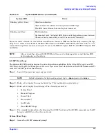
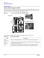
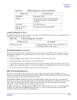
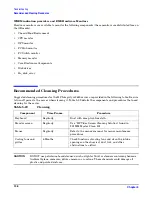
If an iLO MP is installed, the boot process will be monitored by the iLO MP. The diagnostic LEDs are
disabled. See Figure 5-2 for more information.
Figure 5-2
Diagnostic LEDs
The pattern of illuminated LEDs may be used to identify the category of the fault or warning. For example, if
diagnostic LED one is red, there is a problem with memory. However, if diagnostic LEDs one and two are both
red, there is a problem with the server processor.
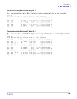
If the diagnostic LEDs indicate an error, check the EFI shell command line interface (CLI) cli>sl e to display
the SEL for a more detailed explanations of the failure.
•
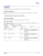
The server LED indicates the severity of the error. Check the server LED before proceeding to analyze the
sequence of diagnostic LEDs:
•
System LED blinking YELLOW indicates a WARNING.
•
System LED blinking RED indicates a FAULT.
•
The diagnostic LEDs provide details about the specific error:
•
Solid red indicates the failing part or subsystem.
•
Off or solid green diagnostic LEDs provide additional details about the failure.
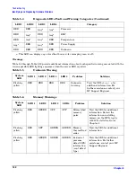
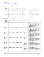
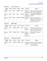
The faults and warnings fall into several general categories. See Table 5-4 for more information.
Table 5-4
Diagnostic LEDs Fault and Warning Categories
LED1
LED2
LED3
LED4
Category
RED
Any
a
Any
a
Any
a
Memory
Any
a
RED
Any
a
Any
a
Firmware
Any
a
Any
a
RED
Any
a
System Board
Any
a
Any
a
Any
a
RED
Fan
1
2
3
4
LAN System
System
LED
Power On/Off
LED
Power On/Off
Button
Diagnostics
LEDs
LAN
LED
Locator
Button and
LED
LED 4
LED 1
LED 3
LED 2


