


Chapter 5
Troubleshooting
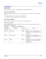
LAN LEDs
132
LAN B Connector LEDs
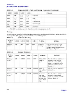
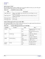
The 1Gb LAN B interface provides two LEDs on the rear panel (the LED on the left is not used). Table 5-24
details the LED locations and states for the LAN B connector.
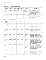
Optional Management Processor LAN LEDs
Four iLO MP LAN LEDs are also on the rear panel if the server has an iLO MP installed. Table 5-25 details
the LED locations and states for the LAN A connector.
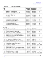
Table 5-24
Gb LAN B Connector LEDs
LED
Description
Speed (upper left)
Yellow—the 1000 MHz with ethernet protocol and twisted-pair wiring is
enabled, off—no link
Speed (upper left)
Green—the 100 MHz with ethernet protocol and twisted-pair wiring is
enabled, off—no link
Link (upper right)
Green—link
Link (upper right)
Off—No link
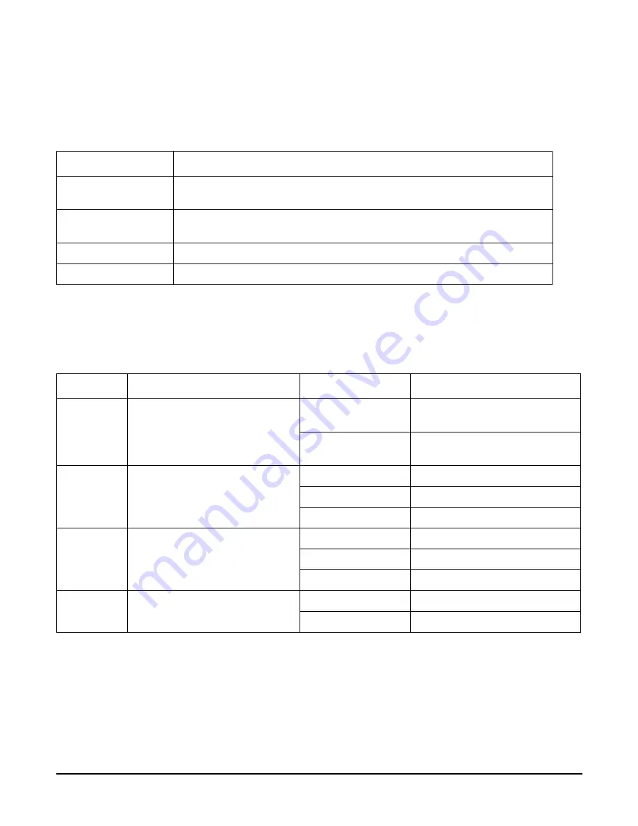
Table 5-25
Optional Management Processor LAN LEDs
LAN LED
Location
Color
State
Self-test
Top
Yellow
Management processor running
selftest or error
Off
Management processor has
booted
10BT
2nd from top
Green
10BT link established
Blinking green
10BT activity
Off
No link or 100BT link
100BT
2nd from bottom
Green
100BT link established
Blinking green
100BT activity
Off
No link or 10BT link
Standby
Power
Bottom
Green
Standby Power on
Off
Standby Power off


