


Controls, Ports, and LEDs
Rear Panel
Chapter 2
36
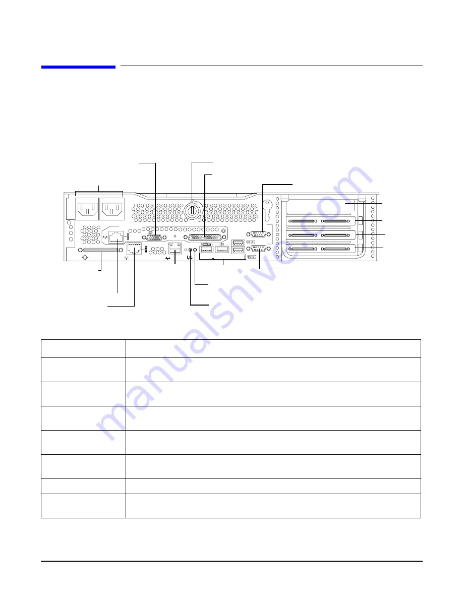
Rear Panel
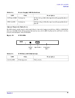
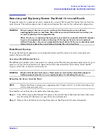
The HP Integrity rx2620 server rear panel includes communication ports, I/O ports, AC power connectors,
and the locator LED/button. Additional LEDs located on the rear panel of the server signal the operational
status of the LAN connector of the optional iLO MP. See Figure 2-6 and Table 2-6 for the location and
description of the ports and connectors.
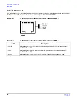
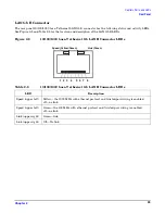
Figure 2-6
Rear View
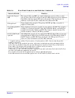
Table 2-6
Rear Panel Connectors and Switches
Connector/Switch
Function
AC Power
Primary power connection (AC1) for the server. A second connector (AC2) is
available for the optional, N+1 redundant power supply.
LVD/SE SCSI
68-pin, low-voltage differential, single-ended U320 SCSI. This connector provides
external SCSI connection on Core SCSI Channel B
(LAN Gb A)
10/100/1000 LAN
10/100/1000 base-T ethernet LAN connector
(LAN Gb B)
10/100/1000 LAN
10/100/1000 base-T ethernet LAN connector
Serial A (console)
and Serial B
9-pin male serial connectors. Serial Port A is used as the console connection when
the optional iLO MP is not installed.
USB
Four universal serial bus (USB 2.0) connectors
TOC
Transfer of control button. Halts all system processing and I/O activity and
restarts the computer system preserving system memory contents.
SCSI LVD/SE
Management Card
LAN Gb A
VGA
PWR
1
2
PWR
LAN Gb B
LAN 10/100
SERIAL A
SERIAL B
CONSOLE
MP
RESET
Automatic Internal SCSI Termination
WARNING Unplug all power cords from system before servicing
TOC
CONSOLE / REMOTE / UPS
USB
AC Power Receptacles
LVD/SE SCSI
10/100
Management LAN
LAN Gb A
10/100/1000 LAN
VGA Port
LAN Gb B
10/100/1000
LAN
USB Ports
System Lock
Console/Serial Port A
Locator Button and LED
ToC Button
Serial Port B
Console/Remote/UPS
PCI Slot 1
PCI Slot 2
PCI Slot 3
PCI Slot 4
AC 1
AC 2
PCI Slot 4


