


Removing and Replacing Components
Location of Internal Components and Connectors
Chapter 4
47
Location of Internal Components and Connectors
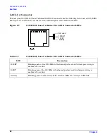
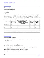
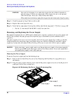
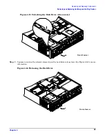
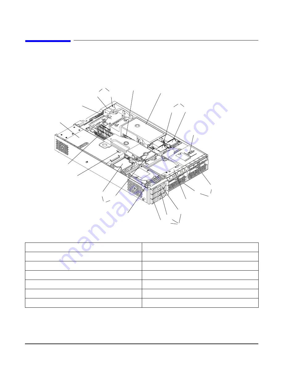
Figure 4-1 and Table 4-1 show the location of the internal server components.
Figure 4-1
Internal Physical Layout
Table 4-1
Component Locations
1 Power receptacles (PWR 1 right, PWR 2 left)
8 Hot-pluggable hard drives (up to 3)
2 Memory airflow guide
9 Hard disk lock
3 Processor airflow guide
10 System fans (fan 2 - memory, fan 3 - I/O cage)
4 System fans (fan 1A - right, fan 1B - left)
11 Intrusion switch
5 Slimline optical drive
12 Memory sockets
6 Power supplies (PSU1 center; PSU2 to the right)
13 PCI cage
7 Status panel board
14 Management controller (Optional)
1
2
3
4
5
7
8
9
10
14
13
12
11
6
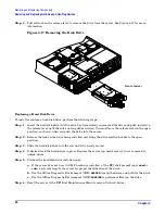
Fan 1A
Fan 1B
PS 2
Drive 0
Drive 1
Drive 2
Pwr 2
Pwr 1
PS 1
Fan 3
Fan 2
Front of server


