


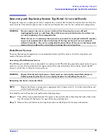
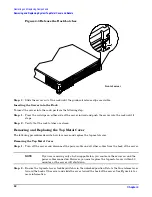


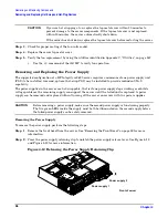


Removing and Replacing Components
Location of Internal Components and Connectors
Chapter 4
48
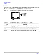
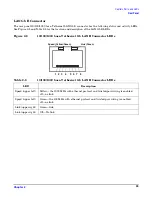
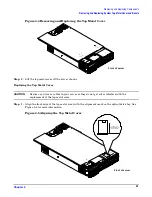
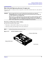
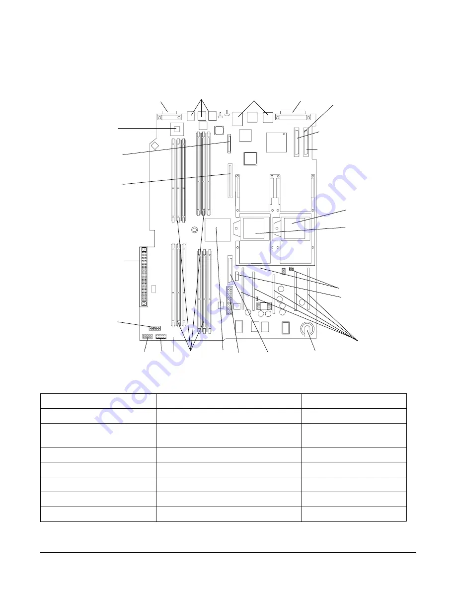
Figure 4-2 shows the location of the connectors and slots on the system board.
Figure 4-2
System Board Connectors and Slots
Table 4-2
Connector Locations
1 External SCSI connector
9 PDH connectors
17 PCI backplane connector
2 SCSI connectors A and B
10 Power module power connector
18 Optical drive connector
3 CPU 0 slot
11 ZX1 memory and I/O controller
(under heatsink)
19 iLO hardware connector
4 CPU 1 slot
12 Memory sockets
20 HP ZX1 I/O adapter
5 Turbo fan power connectors
13 Status panel connector
21 Serial ports (2)
6 Fan Connector
14 Power module auxiliary connector
22 USB connectors (4)
7 Five VRM cards
15 SCSI backplane power connector
23 LAN connectors (2)
8 Battery
16 PCI/memory fan cable connector
1
2
4
3
8
9
10
16
14 13
12
11
5
15
17
18
19
20
21
22
23
7
SCSI Ch A
SCSI Ch B
Front of server
6


