


Removing and Replacing Components
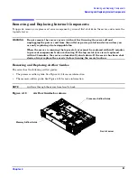
Removing and Replacing Internal Components
Chapter 4
68
Step 5.
Replace the server top metal cover, reconnect all cables and turn on the server.
Step 6.
Verify that the newly installed memory works:
•
Run the
info mem
command at the EFI shell prompt, or
•
Run
memdiag
from the Offline Diagnostics CD to insure that the memory is functional
•
Monitor the System Event Log (SEL) to ensure there are no events showing memory problems.
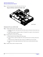
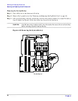
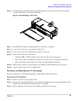
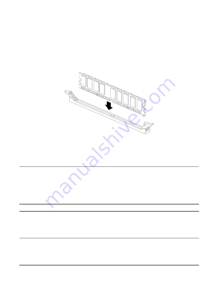
Figure 4-24
Inserting DIMM into Slot
Removing and Replacing a Processor
This section provides information about removing and replacing a processor. The processors are located on the
system board, which is accessible by removing the top metal cover.
WARNING
Ensure that the server is powered-down and all power sources have been
disconnected from the server prior to removing or replacing a processor.
Voltages are present at various locations within the server whenever an AC power
source is connected. This voltage is present even when the main power switch is in
the off position.
Failure to observe this warning could result in personal injury or damage to
equipment
CAUTION
Failure to properly complete the steps in this procedure will result in erratic server behavior or
server failure. For assistance with this procedure contact your local HP Authorized Service
Provider.
Observe all ESD safety precautions before attempting this procedure. Failure to follow ESD
safety precautions could result in damage to the server.
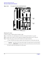
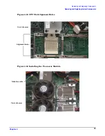
The processors are located on the system board. The system board can support either one or two processors.
The CPU 0 slot is located on the right side of the system board, and the CPU 1 slot is located to the left of
CPU 0 near the memory DIMMs. See Figure 4-25 for the processor locations.


