


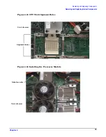


Removing and Replacing Components
Removing and Replacing Internal Components
Chapter 4
72
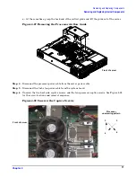
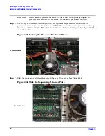
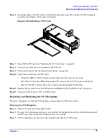
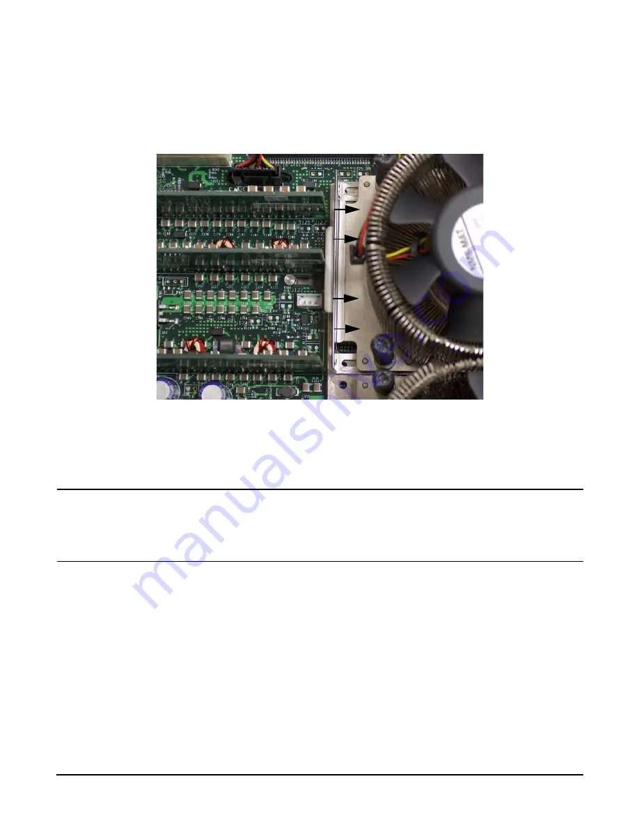
Step 7.
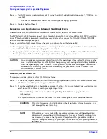
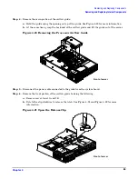
Slide the sequencing retainer plate toward the back of the server to open the hole in the edge of the
heatsink for insertion of the special processor tool into the processor module locking mechanism.
See Figure 4-29 for more information.
Figure 4-29 Slide Sequencing Retainer Plate
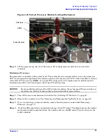
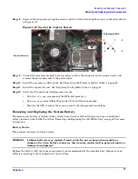
Step 8.
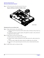
Unlock the processor-locking mechanism using the special processor tool (P/N 5069-5441), or
equivalent 2.5 mm hex tool, shipped with your replacement processor assembly. Insert the tool
through the turbo fan blades into the lock and rotate the processor tool 180 degrees
counterclockwise. See Figure 4-30 for more information.
CAUTION
The zero insertion force (ZIF) socket for the processor is locked and unlocked by 1/2 of
a full turn of the 2.5 mm hex tool. The counterclockwise 180 degree rotation (1/2
turn) unlocks the socket. A clockwise 180 degree rotation locks the socket.
Attempting to turn the locking mechanism more that 180 degrees will severely
damage the socket.
Front of server


