


Removing and Replacing Components
Removing and Replacing Internal Components
Chapter 4
73
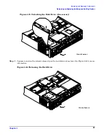
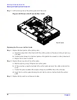
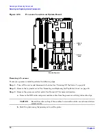
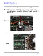
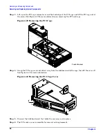
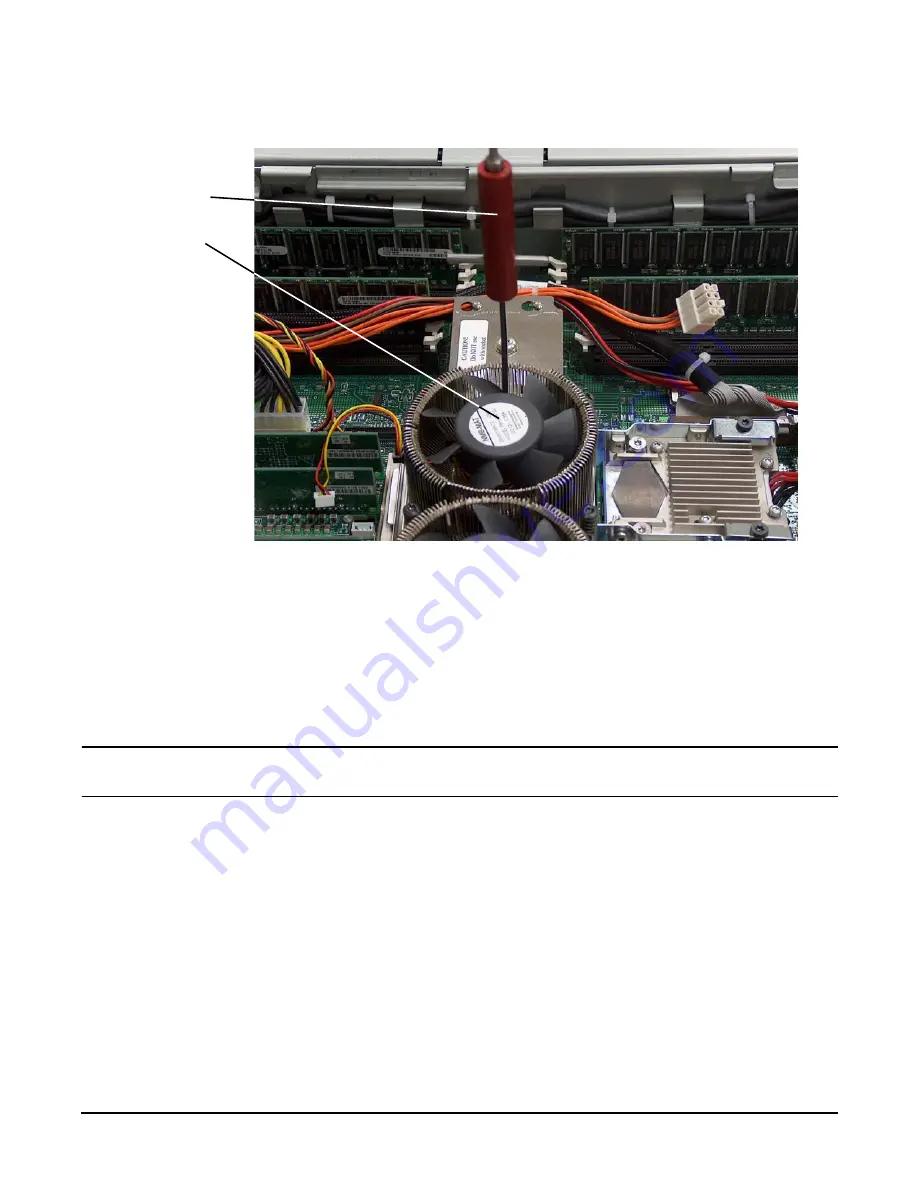
Figure 4-30 Unlock Processor Module Locking Mechanism
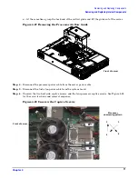
Step 9.
Lift the processor up and out of the chassis. Place the processor module into an anti-static
container.
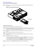
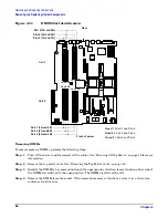
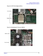
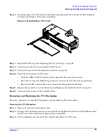
Replacing a Processor
The processors are located on the system board. The system board can support either one or two processors.
CPU 0 is located on the right side of the system board near the chassis, and CPU 1 (when installed) is located
to the left of CPU 0 near the DIMMs. In a single CPU configuration, the single processor module must be
installed in the CPU 0 slot. See Figure 4-26 for the CPU slot locations.
CAUTION
Do not modify the settings of the DIP switches located on the system board. These switches are
for factory use. Failure to observe this caution will result in server failure.
Step 1.
Turn off the server and disconnect all cables. See “Powering Off the Server” on page 42.
Step 2.
Remove the top metal cover. See “Removing and Replacing the Top Metal Cover” on page 50.
Step 3.
If you are replacing a processor module, remove the old processor as described “Removing a
Processor” on page 70.
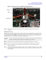
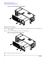
Step 4.
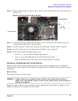
Verify the ZIF socket lock is unlocked by looking at the CPU socket. The thicker post on the locking
mechanism should be pointed toward the unlock symbol on the ZIF socket. Figure 4-33 shows the
socket unlocked.
Front of server
CPU tool
CPU 1


