


Removing and Replacing Components
Removing and Replacing Internal Components
Chapter 4
74
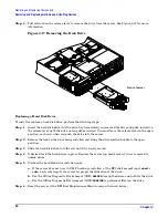
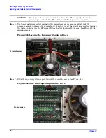
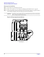
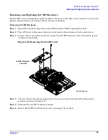
Figure 4-31 Unlocked ZIF Socket Lock
CAUTION
The zero insertion force (ZIF) socket for the processor is locked and unlocked by 1/2 of
a full turn of the 2.5 mm hex tool. The counterclockwise 180 degree rotation (1/2
turn) unlocks the socket. A clockwise 180 degree rotation locks the socket.
Attempting to turn the locking mechanism more that 180 degrees in either direction
will severely damage the socket.
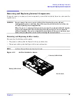
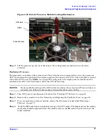
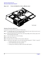
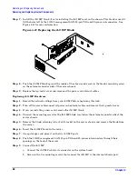
Step 5.
Use the two alignment pins on the processor to properly align the processor on the system board.
The two alignment pins fit in the alignment holes on the system board processor mount.
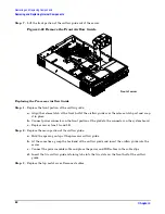
Figure 4-32 shows the location of the alignment pins on the processor. Figure 4-33 shows the
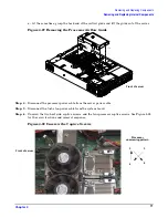
alignment holes on the system board. The turbo fan power cable must be positioned so that it is
located on the side of the heatsink that faces the front of the server. Figure 4-34 shows the
processor on the system board.
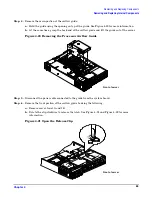
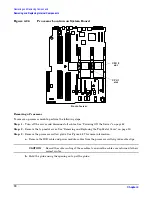
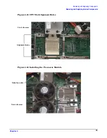
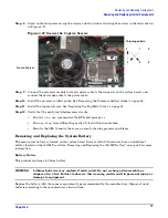
Figure 4-32 Processor Alignment Pins
Front of server
CPU 1 ZIF socket
lock (unlocked)
Alignment pins
Front of server


