


Removing and Replacing Components
Removing and Replacing Internal Components
Chapter 4
77
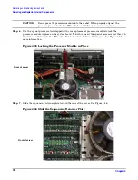
Step 8.
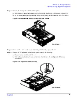
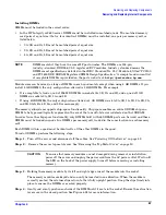
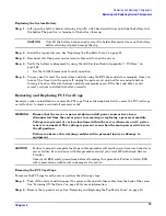
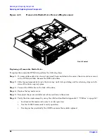
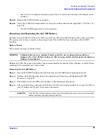
Screw in the four processor captive screws, and the two heat sink captive screws in the order shown
in Figure 4-37.
Figure 4-37 Secure the Captive Screws
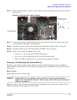
Step 9.
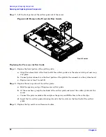
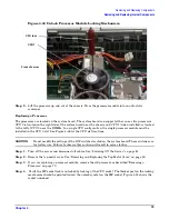
Connect the processor module turbo fan power cable to the connector on the system board, and
connect the power pod cable to the power cable
Step 10.
Install the processor airflow guide. See “Removing the Processor Airflow Guide” on page 62.
Step 11.
Install the top metal cover. See “Replacing the Top Metal Cover” on page 51.
Step 12.
Verify that the newly installed processor works:
•
Run the
info cpu
command at the EFI shell prompt; or
•
Run
cpu diag
from Offline Diagnostic CD for full functional check.
•
Monitor the SEL to ensure there are no events showing processor problems.
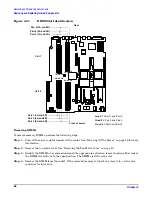
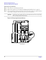
Removing and Replacing the System Battery
The main server battery is located on the system board. Servers with iLO hardware have an additional
battery located on the iLO MP card. See “Removing and Replacing the iLO MP Battery” on page 89 for more
information.
Battery Notice
This product contains a Lithium battery.
WARNING
Lithium batteries may explode if mistreated. Do not recharge, disassemble, or
dispose of in a fire. Failure to observe this warning could result in personal injury or
damage to equipment.
Replace the battery with the same or equivalent type recommended by the manufacturer. Dispose of used
batteries according to the manufacturer's instructions.
Torquing pattern
Front of server
1
4
3
2
1
2
3
5
6
4
5
6


