


Removing and Replacing Components
Removing and Replacing Internal Components
Chapter 4
92
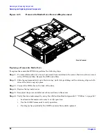
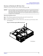
Replacing the LED Status Panel
Step 1.
Replace the LED status panel in the server and screw in the two LED status panel mounting
screws.
Step 2.
Connect the LED status panel controller cable.
Step 3.
Replace the top metal cover and reconnect all power cables. Turn on the server and verify that the
server and power LEDs light up.
Step 4.
Copy a valid UUID to the new status panel.
NOTE
If resetting the UUID does not work successfully, contact your HP support
representative.
Step 5.
Verify the display panel replacement by exercising all front panel controls and observing that the
display panel LEDs are operating properly.
Removing and Replacing the System Board
CAUTION
Some server settings are saved to the LED status panel. If you are replacing both the LED
status panel and the system board, they must be replaced one at a time to avoid loss of server
settings. First replace one component, then turn on the server and boot to the EFI prompt.
After confirming that the first component has been replaced successfully, shut down the server
and replace the second component.
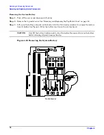
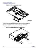
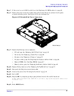
Removing the System Board
Step 1.
Turn off the server, disconnect all power and external cables and remove the top metal cover.
Step 2.
Remove these components from the system board:
•
Memory airflow guide. See “Removing the Memory Airflow Guide” on page 62
•
Memory DIMMs. See “Removing DIMMs” on page 66
•
Processor airflow guide. See “Removing the Processor Airflow Guide” on page 62
•
Processors. See “Removing a Processor” on page 70
•
Server fans 1A, 1B, 2, and 3. See “Removing a Server Fan” on page 54
•
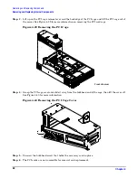
PCI card cage. See “Removing the PCI Card Cage” on page 79
Step 3.
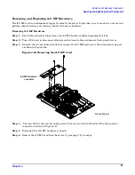
If the server has iLO MP hardware installed, remove it as described in “Removing iLO MP
Hardware” on page 87.
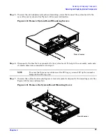
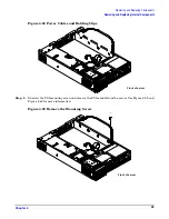
Step 4.
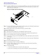
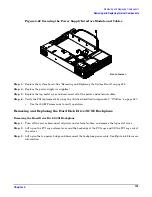
Remove the power connector plate:
a.
Unscrew the two power connector mounting screws on the back of the server.
b.
Reach inside the server to remove the power connectors from the socket. The power connectors
should still be connected to their cables.