Chapter 6
Replacing Parts
96
3. Pull the chassis out of the rack.
CAUTION
Wear a wrist-strap and use a static-dissipating work surface connected to the
chassis when handling components. Ensure the metal of the wrist-strap contacts
your skin.
4. Loosen the two thumbscrews in the back of the chassis that secure the rear cover.
5. Read the documentation included with the accessory board and follow any special instructions.
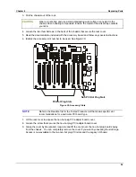
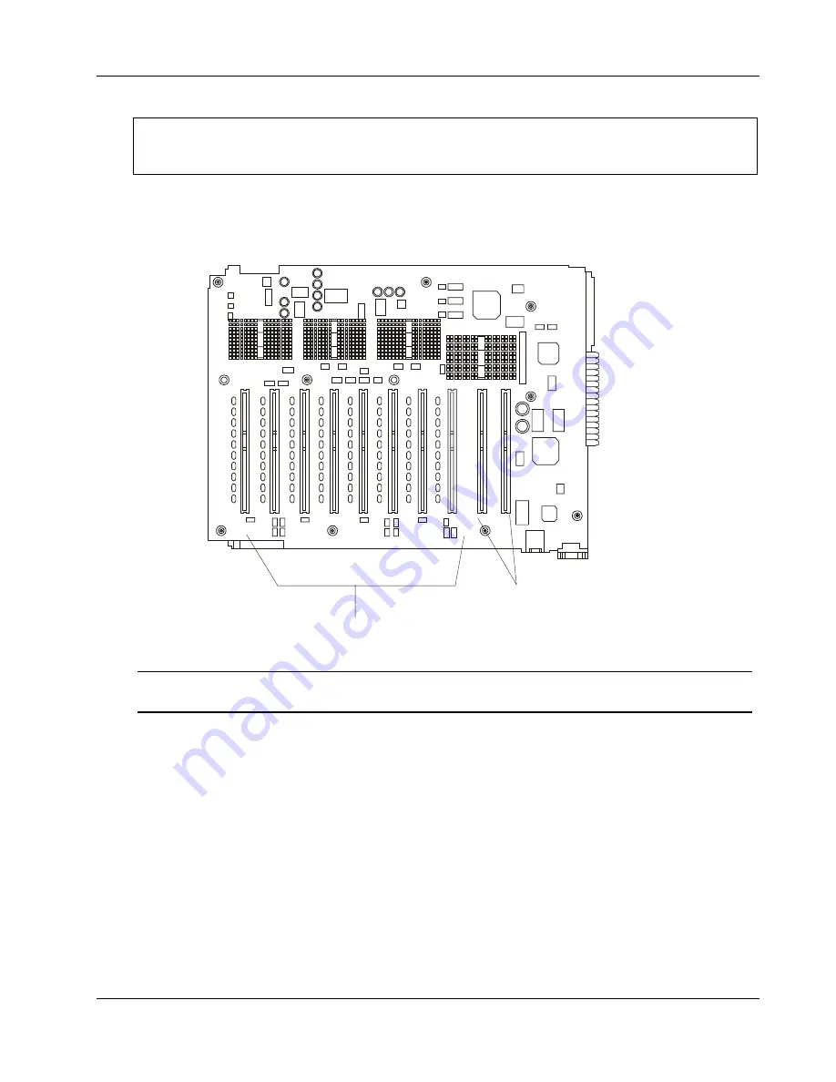
6. Identify the accessory slot number to be used. See Figure 30.
PCI Hot Plug Slots
Non PCI Hot Plug Slots
Figure 30. Accessory Slots
NOTE
Refer to the Readme file for the Tested Products List that shows specific slot
recommendations for a particular PCI board type.
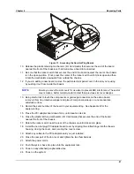
7. Lift the rear cover to expose the non-hot plug PCI adapter board cover.
8. Loosen the screw that secures the non-hot plug PCI adapter board cover.
9. Grasp the cover by its exposed, long side and lift the cover over the non-hot plug boards away
from the chassis. You can completely remove the cover if you want by unseating the slot hinge.
Access is now available to the two non-hot plug PCI slots and the Legacy I/O board.
Summary of Contents for Integrity rx4610
Page 1: ...hp server rx4610 Service Manual Online Version 1 0 Last Updated June 2001 ...
Page 8: ...8 ...
Page 16: ...Chapter 1 General Information 8 ...
Page 38: ......
Page 86: ......
Page 144: ...Chapter 6 Replacing Parts 136 ...

