


Chapter 6
Replacing Parts
109
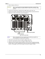
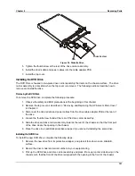
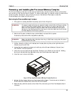
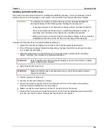
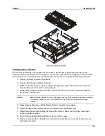
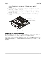
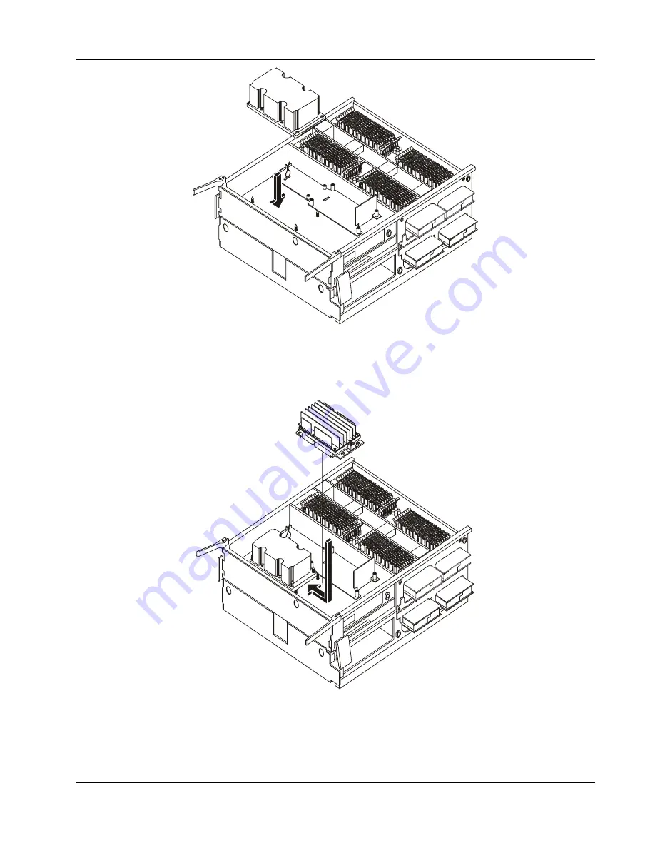
Figure 39. Installing the Microprocessor
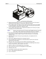
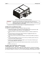
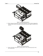
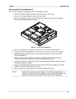
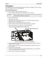
10. Place the power pod into position on the Processor Baseboard. Ensure that the engaging tab is
to the rear of the retention module (RM) and then slide it forward to engage its connector on the
processor.
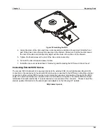
Figure 40. Connecting the Power Pod
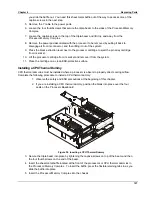
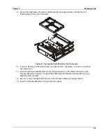
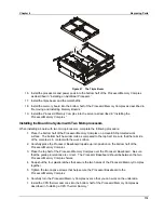
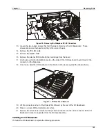
11. Place the triple beam into position by lowering it down over the processors/power pod or the
CPU thermal dummy.
Summary of Contents for Integrity rx4610
Page 1: ...hp server rx4610 Service Manual Online Version 1 0 Last Updated June 2001 ...
Page 8: ...8 ...
Page 16: ...Chapter 1 General Information 8 ...
Page 38: ......
Page 86: ......
Page 144: ...Chapter 6 Replacing Parts 136 ...


