Chapter 6
Replacing Parts
115
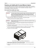
Removing and Installing the Memory Board DC-to-DC Converters
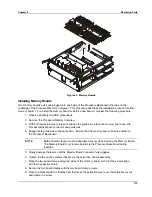
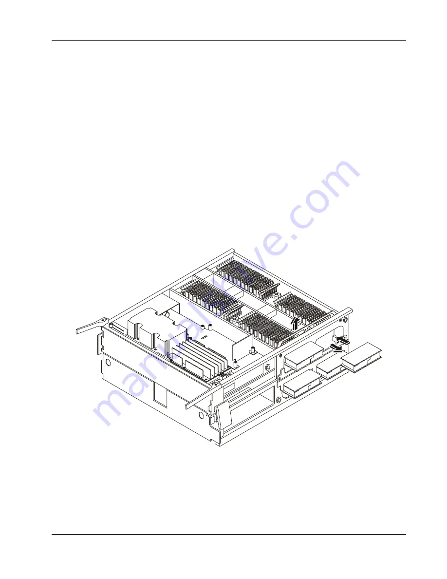
The Memory Board DC-DC Converters reside on the side of the Processor/Memory Complex inside the
system chassis. The server uses four converters to supply regulated power to the Processor/Memory
Complex. You can access them by removing the Processor/Memory Complex and working from its side.
The Memory Board DC-to-DC Converters must be removed before the Memory Board can be replaced.
Removing the Converters
To remove the converters, complete the following procedure:
1. Observe the necessary safety and ESD precautions.
2. Remove the Processor/Memory Complex.
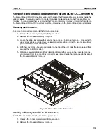
3. Loosen the slide clamp screw that secures the converters but do not remove it. Loosening the
upper screw allows you to remove the upper converters, while loosing the lower screw allows
you to remove the lower converters.
4. With the converters to be removed located on the top of the unit, slide the clamp upward that
secures that pair of converters.
5. Pull each converter straight out from its socket. Be sure that you keep the converter level as
you remove it from its socket. Each converter has a keyed guide that is attached to the side of
the Processor/Memory Complex.
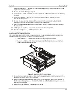
Figure 44. Memory Board DC-DC Converters
Installing the Memory Board DC-to-DC Converters
To install the converters, complete the following procedure:
1. Observe the necessary safety and ESD precautions.
2. Remove the Processor/Memory Complex.
Summary of Contents for Integrity rx4610
Page 1: ...hp server rx4610 Service Manual Online Version 1 0 Last Updated June 2001 ...
Page 8: ...8 ...
Page 16: ...Chapter 1 General Information 8 ...
Page 38: ......
Page 86: ......
Page 144: ...Chapter 6 Replacing Parts 136 ...

