


Chapter 6
Replacing Parts
116
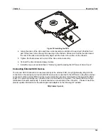
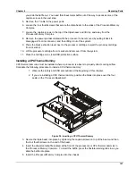
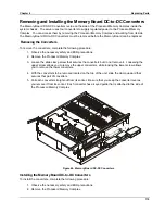
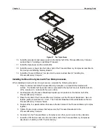
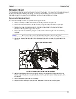
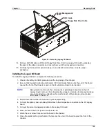
3. Carefully align the Processor DC-to-DC converter’s plug with the socket on the
Processor/Memory Complex assembly and press it firmly into place. Be sure to keep the
converter level such that the keyed guide accepts the edges of the bottom PCB on the
converter.
4. Slip the slide clamp up over the converter to secure it in place. Do not tighten the screws until
both pairs of converters have been installed.
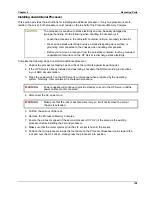
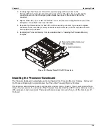
5. Repeat steps three and four for each DC-to-DC converter you install. If you need to replace
converters on the secondary memory board beneath the complex, turn the complex over and
then replace the converters.
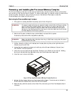
6. Reinstall the Processor/Memory Complex as described in “Installing the Processor/Memory
Complex”.
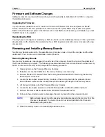
Figure 45. Memory Board DC-to-DC Converters
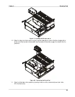
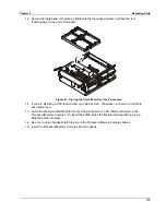
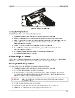
Installing the Processor Baseboard
The Processor Baseboard resides between the two halves of the Processor/Memory Complex. Removal of
the Processor Baseboard involves disassembly of the entire Processor/Memory Complex.
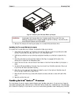
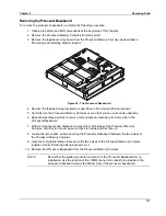
The board can accommodate one to four processors and two memory boards. If your server does not have
three or four processors, the underside of the Processor Baseboard will have CPU thermal dummies in place
of the processors and power pods. These assemblies are easily removed when you lift the triple beam off
the board.
Summary of Contents for Integrity rx4610
Page 1: ...hp server rx4610 Service Manual Online Version 1 0 Last Updated June 2001 ...
Page 8: ...8 ...
Page 16: ...Chapter 1 General Information 8 ...
Page 38: ......
Page 86: ......
Page 144: ...Chapter 6 Replacing Parts 136 ...


