Chapter 6
Replacing Parts
122
I/O Baseboard
The I/O Baseboard resides in the upper rear of the chassis and plugs into the Sideplane. After removing all
the PCI I/O boards, you can remove the I/O Baseboard.
Removing the I/O Baseboard
To remove the I/O baseboard, complete the following procedure:
1. Observe all safety and ESD precautions for handling electronic components.
WARNING
The power supply will continue to provide standby current to the HP Server until the
power cable is disconnected from the rear panel.
2. Power down the HP Server.
3. Disconnect the power cables.
4. Open the rear cover of the server and remove the non-hot plug PCI adapter board cover by
loosening its screw and unhinging the cover.
5. Remove the top cover as described in “Removing the Top Cover.”
6. Remove the Legacy I/O board as described in “Removing the Legacy I/O Board.”
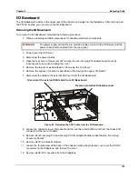
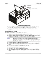
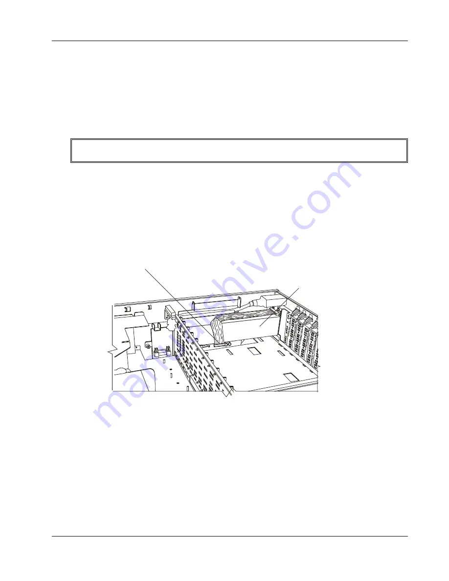
7. Disconnect the cable to the external SCSI port from the I/O Baseboard.
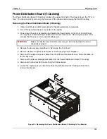
Disconnect the external SCSI cable from I/O Baseboard
Remove protective Sideplane cover
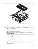
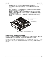
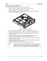
Figure 49. Removing the SCSI Cable from the I/O Baseboard
8. Loosen the captive screw to disconnect and remove the external SCSI port from the chassis I/O
connector at the rear of chassis.
9. Remove all non-hot plug PCI and hot plug PCI I/O adapter boards as described in “Removing
Accessory Boards.”
10. Remove all PCI slot plastic dividers.
11. Loosen the thumbscrew at the back of the chassis holding the protective cover over the DC-DC
converters on the Sideplane, and remove the cover.
12. Remove all DC-DC converters from the Sideplane.
Summary of Contents for Integrity rx4610
Page 1: ...hp server rx4610 Service Manual Online Version 1 0 Last Updated June 2001 ...
Page 8: ...8 ...
Page 16: ...Chapter 1 General Information 8 ...
Page 38: ......
Page 86: ......
Page 144: ...Chapter 6 Replacing Parts 136 ...

