
Chapter 6
Replacing Parts
123
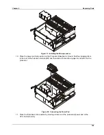
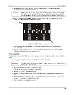
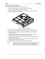
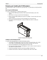
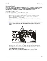
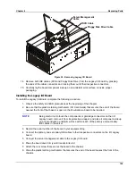
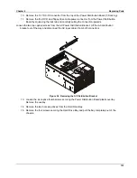
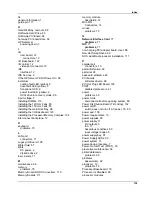
Figure 50. Removing the Sideplane DC-DC Converters
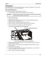
13. Loosen the two captive screws that hold the plastic shield over the I/O Baseboard. These
screws also secure the baseboard tray to the server chassis.
14. Remove the PCI LED cable.
15. Remove the plastic shield.
16. Remove the Internal SCSI cable for the hard drives from the board.
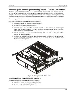
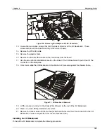
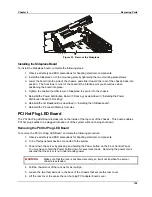
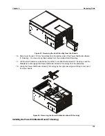
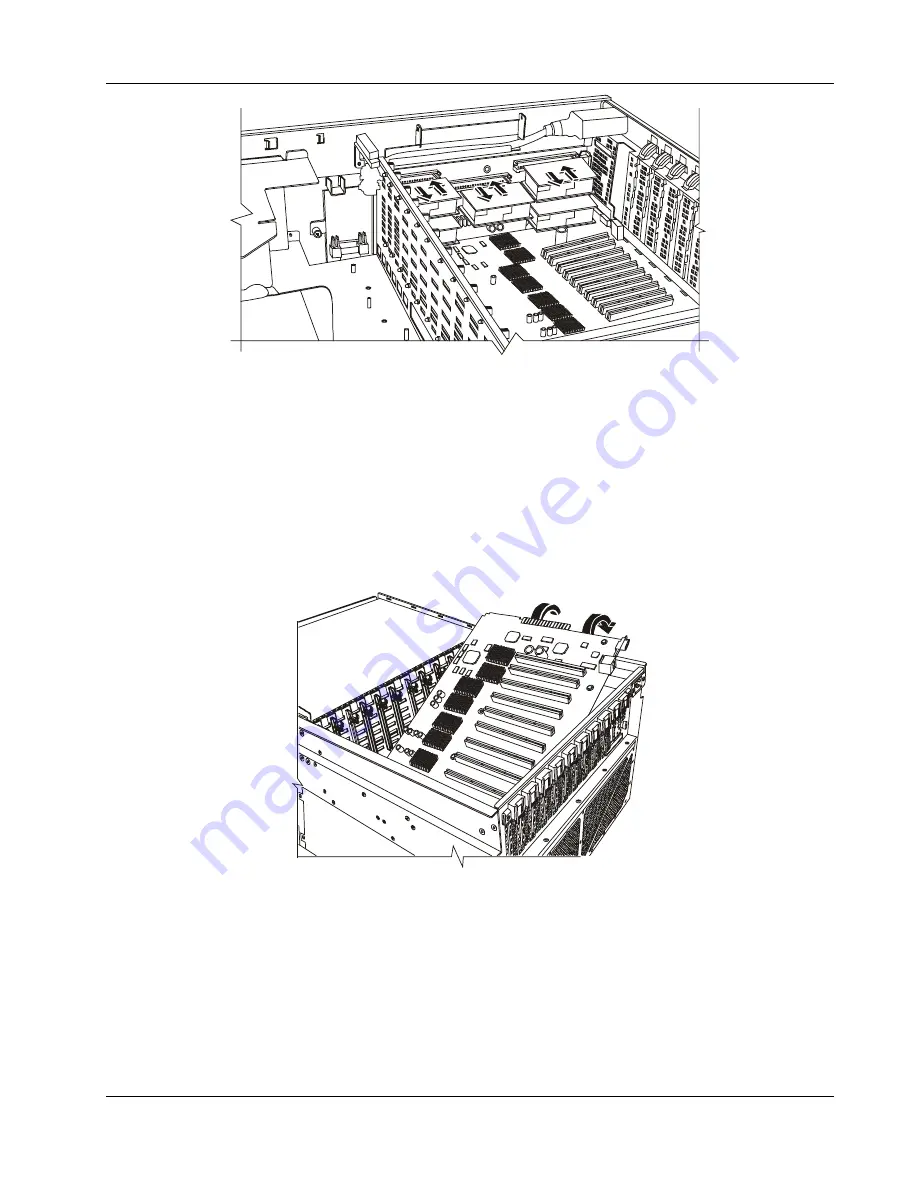
17. Use the two extraction/installation levers on the sides of the I/O Baseboard to pull it clear of the
connector on the Sideplane.
18. Once loose, slide the I/O Baseboard in the direction of the levers against the chassis frame.
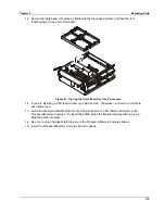
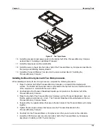
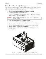
Figure 51. I/O Baseboard Removal
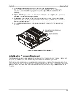
19. Lift the connector end out of the chassis first followed by the rest of the I/O Baseboard.
20. Place on a clean ESD-protected work surface.
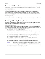
21. Remove the nine screws and the two hex jackscrews that secure the video connector to the I/O
Baseboard in order to separate it from the I/O Baseboard tray.
Installing the I/O Baseboard
To install the I/O Baseboard, complete the following procedure:
Summary of Contents for Integrity rx4610
Page 1: ...hp server rx4610 Service Manual Online Version 1 0 Last Updated June 2001 ...
Page 8: ...8 ...
Page 16: ...Chapter 1 General Information 8 ...
Page 38: ......
Page 86: ......
Page 144: ...Chapter 6 Replacing Parts 136 ...


