
Chapter 6
Replacing Parts
125
Sideplane Board
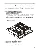
The Sideplane is attached inside the left wall at the rear of the chassis. It receives the I/O Baseboard as well
as the Power Distribution Board (T-Docking). To remove the Sideplane you must remove the Power
Distribution Board (T-Docking), the I/O Baseboard, and the Processor/Memory Complex.
Removing the Sideplane Board
To remove the Sideplane board, complete the following procedure:
1. Observe all safety and ESD precautions for handling electronic components.
2. Remove the I/O Baseboard as described in “Removing the I/O Baseboard” in this chapter.
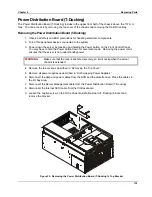
3. Remove the Power Distribution Board (T-Docking) as described in “Removing the Power
Distribution Board (T-Docking)” in this chapter.
4. Remove the Processor/Memory Complex as described in “Removing the Processor/Memory
Complex.”
NOTE
Do not remove the screws that hold the Sideplane to the mounting plate.
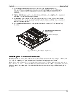
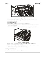
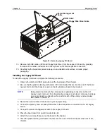
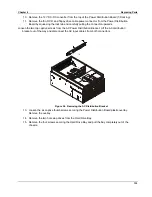
5. Loosen the captive thumbscrews on the Sideplane that secure it and its mounting plate to the
chassis.
Loosen the three captive thumb screws.
Figure 52. Removing the Screws from the Sideplane
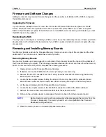
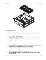
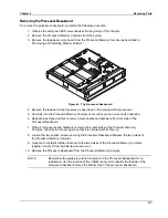
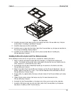
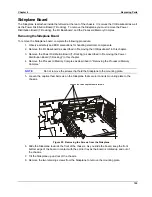
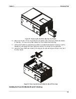
6. Slide the Sideplane towards the front of the chassis. As you slide the board, keep the front
bottom edge of the board in contact with the carrier tray as the board is rotated up and out of
the chassis.
7. Tilt the Sideplane up and out of the chassis.
8. Remove the two retaining screws from the Sideplane to remove the mounting plate.
Summary of Contents for Integrity rx4610
Page 1: ...hp server rx4610 Service Manual Online Version 1 0 Last Updated June 2001 ...
Page 8: ...8 ...
Page 16: ...Chapter 1 General Information 8 ...
Page 38: ......
Page 86: ......
Page 144: ...Chapter 6 Replacing Parts 136 ...


