


Chapter 2
System Information
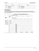
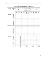
12
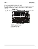
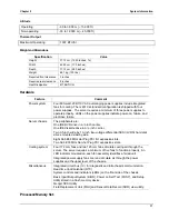
Feature Description
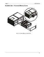
Processor board
The processor board supports up to four Intel
Itanium
processors and 48V power pods.
Intel
Itanium
microprocessor
packaged in a Slot M lift socket.
Installed: Up to four Intel
Itanium
processors, packaged
in Slot M pin array cartridges.
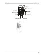
Memory boards
Two plug-in boards containing main memory supporting
PC100 Version 1.2 buffered SDRAM. Each memory board
supports from 1 GB to 32 GB of error correction code
memory using 32 72-bit dual inline memory modules. The
boards interface to the processors via connectors on each
side of the processor board.
I/O baseboard
Eight 64-bit/66 MHz Hot Plug PCI slots.
Two 64-bit/33 MHz Non-hot Plug PCI slots.
ATI RAGE
†
XL PCI super video graphics array controller
with 16 MB of video memory.
The QLogic
†
ISP 12160 LVDS SCSI controller supports two
LVDS channels. One channel is used internally to provide
support for the internal SCSI drives (connected to the LVDS
disk backplane). The second LVDS channel is routed to the
rear of the chassis to support external devices.
This board contains all legacy I/O connections and plugs
into an edge connector on the I/O baseboard.
PS/2-compatible keyboard and mouse ports.
PS/2-compatible parallel port.
The PCI-enhanced Integrated Drive Electronics interface
has two IDE buses, supporting the diskette drive (Primary
IDE 0) and DVD drive (Secondary IDE 1).
Two universal serial bus ports.
Legacy I/O board
Two PS/2-compatible, 9-pin serial ports.
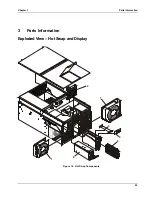
SCSI Hot Swap backplane
This backplane supports up to two 1-inch SCA2-type LVDS
SCSI drives, mounted in carriers.
The front panel board provides the user interface to the
server.
Push-button switches control power-up, reset, and
initialization functions.
LEDs indicate power on, power supply failure, hard drive
failure, or a fan failure.
Front panel board
An LCD panel provides information about boot status,
available number of processors.
Sideplane Board
The Sideplane board:
Electrically connects the processor board and I/O
baseboard. Interconnects to the Power Distribution board.
Contains the sockets for the 5 V and 3.3 V DC-to-DC
converters.
Distributes DC power to the power bay, I/O bay, and
docking board.
Power Distribution Board
Distributes the power load of the server among four 800-
watt autoranging power supplies.
Summary of Contents for Integrity rx4610
Page 1: ...hp server rx4610 Service Manual Online Version 1 0 Last Updated June 2001 ...
Page 8: ...8 ...
Page 16: ...Chapter 1 General Information 8 ...
Page 38: ......
Page 86: ......
Page 144: ...Chapter 6 Replacing Parts 136 ...


