Chapter 6
Replacing Parts
90
Hot Swapping Power Supplies
In a fully configured system, the power system contains four 800-watt autoranging power supplies. The third
bay’s power supply serves a redundancy function for the server’s power supply requirements.
CAUTION
Because of chassis airflow disruption, the power supply bay should not be vacant for
more than five minutes when server power is on. Exceeding the five-minute limit
might cause system cooling to fall below the minimum required level and possibly
cause damage to system components.
NOTE
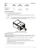
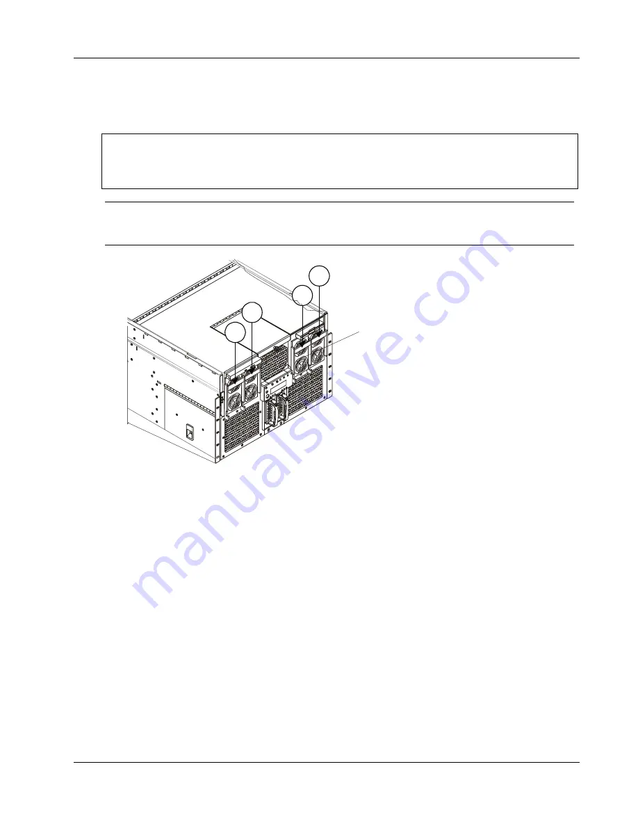
If you have only three supplies installed, they must occupy the first, second, and
fourth power supply bays as you face the chassis. Figure 26 shows the power
supply installation order.
1
3
4
2
If only 3 power supplies
are operational, place a
filler panel over the fourth
bay in the installation order.
Figure 26. Power Supply Installation Order
Determining Power Supply Status
When the amber power supply failure LED on the front of the chassis turns on, determine which power
supply is defective by checking the three status LEDs on each supply. Each power supply has three LEDs
that both indicate whether power is supplied to the power supply and the health of the power supply. The
LEDs are ordered top to bottom on each power supply. Table 6-1 illustrates the states indicated by the three
LEDs.
Table 6-1. Power Supply LEDs
Power
Supply
Status
PWR
(Green)
(Top Position)
PFAIL
(Amber)
(Middle Position)
FAIL
(Amber)
(Bottom Position)
No AC power to any
power supplies
Off Off
Off
No AC power to a
specific power supply
Off Off
On
AC present / Standby
output on
Blinking Off
Off
DC outputs on and
On
Off
Off
Summary of Contents for Integrity rx4610
Page 1: ...hp server rx4610 Service Manual Online Version 1 0 Last Updated June 2001 ...
Page 8: ...8 ...
Page 16: ...Chapter 1 General Information 8 ...
Page 38: ......
Page 86: ......
Page 144: ...Chapter 6 Replacing Parts 136 ...

