Chapter 6
Replacing Parts
107
you slide the baffle out. You need this sheet metal baffle out of the way to access some of the
captive screws in the next step.
5. Remove the Y cable to the power pods.
6. Loosen the four thumbscrews that secure the triple-beam to the sides of the Processor/Memory
Complex.
7. Loosen the captive screws in the top of the triple-beam and lift it up and away from the
Processor/Memory Complex.
8. Remove the power pod associated with the processor to be removed by pulling it back to
disengage it from its connector, and then lifting it out of the system.
9. Press the black extraction lever next to the processor cartridge to eject the pin array cartridge
from its socket.
10. Lift the processor cartridge from its socket and remove it from the system.
11. Place the cartridge on a clean ESD-protective surface.
Installing a CPU Thermal Dummy
CPU thermal dummies must be installed where a processor is absent to properly direct cooling airflow.
Complete the following procedure to install a CPU thermal dummy:
1. Observe the safety and ESD precautions at the beginning of this chapter.
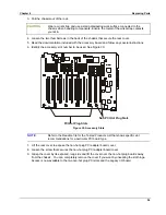
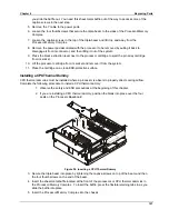
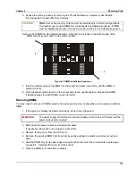
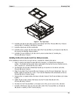
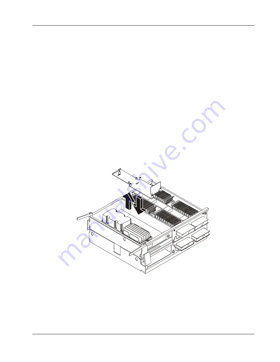
2. If you are installing a CPU thermal dummy, position the blank into place over the four
posts on the Processor Baseboard.
Figure 38. Inserting a CPU Thermal Dummy
3. Secure the triple beam into place by tightening the captive screws on top of the beam and then
the four thumbscrews on the end of the beam.
4. Insert the sheet metal baffle located at the front of the processors or CPU thermal dummies in
the Processor/Memory Complex. To insert the baffle, press the flexible retaining tabs in as you
slide the baffle into place
5. Insert the Processor/Memory Complex into the chassis.
Summary of Contents for Integrity rx4610
Page 1: ...hp server rx4610 Service Manual Online Version 1 0 Last Updated June 2001 ...
Page 8: ...8 ...
Page 16: ...Chapter 1 General Information 8 ...
Page 38: ......
Page 86: ......
Page 144: ...Chapter 6 Replacing Parts 136 ...

