Chapter 6
Replacing Parts
127
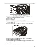
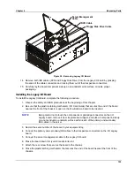
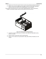
7. Loosen the screw that secures the non-hot plug PCI adapter board cover.
8. Grasp the cover by its exposed, long side and lift the cover away from the chassis. You can
completely remove the cover if you want by unseating the slot hinge. Access is now available
to the PCI Hot Plug LED Board.
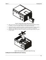
9. Disconnect the cable attached to the PCI Hot Plug LED Board.
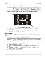
10. Locate and remove the four small, black plastic retaining pins on the board. The pins are
evenly spaced across the length of the board. To unlock the pin, grasp the head of the pin from
the inside and pull it until it clicks.
11. Carefully pull the PCI Hot Plug LED Board away from the inside of the chassis and place it on
an antistatic surface.
Installing the PCI Hot Plug LED Board
To install the PCI Hot Plug LED Board, complete the following steps:
1. Observe all safety and ESD precautions for handling electronic components.
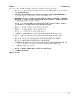
2. Carefully place the PCI Hot Plug LED Board on the inside back of the server chassis in such a
way as to line up the four, black pin receptacles with their respective holes.
NOTE
It is suggested that you place a piece of paper on the inside of the chassis just
below the board as you insert the black retaining pins as a safeguard should they
slip from your fingers.
3. Press the pins through the holes in the board and through their receptacles in the chassis.
4. Connect the cable to the PCI Hot-Plug LED Board.
5. Attach the non-hot plug PCI adapter board cover to the chassis and secure it with the screw.
6. Close the rear part of the top cover and secure it by tightening the two thumbscrews in the back.
7. Install the power cords.
8. Push the server back into the equipment rack.
9. Power-on the system.
10. Turn on all peripheral devices connected to the system that you shut down during this
procedure.
Summary of Contents for Integrity rx4610
Page 1: ...hp server rx4610 Service Manual Online Version 1 0 Last Updated June 2001 ...
Page 8: ...8 ...
Page 16: ...Chapter 1 General Information 8 ...
Page 38: ......
Page 86: ......
Page 144: ...Chapter 6 Replacing Parts 136 ...

