background image

Hub Operation

Front of the Hub

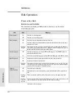
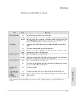
Hub Status and Port LEDs    

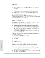
The hub status and LAN port LEDs indicate whether or not the hub is
functioning properly. 

LED

State

Meaning

Power (green) 

On

The hub is receiving power.

Off

The hub is not receiving power.

Fault  (orange) 

Off

Self tests have not detected any faults on the hub.

On

The hub or Expansion Slot module has failed its self-test after the hub has been
powered on or reset.  

Flashing

Slowly*

If the bridge module is installed, this LED indicates a problem with the 10Base-T
connection or part of the module itself.  Otherwise, this LED should only occur in
tandem with the RPS LED indicating an RPS failure.

Console  (green) 

Off

The hub is not being accessed by HP Stack Manager or if an SNMP module is
installed, the ASCII console.

On

This hub is currently being accessed by HP Stack Manager or the ASCII console.

Exp Slot (green)  

On

An optional module is properly installed in the hub’s back panel slot.

Off

An optional module is not installed.

Flashing

Slowly*

The module is performing its self-test (after hub power on or a reset). If the rate
of flashing increases and the flashing continues for more than approximately 30
seconds, refer to chapter 3, “Troubleshooting”. 

Uplink A, 
Uplink B (green)

Off

The Uplink port is disabled.

On

The Uplink port is connected and has successfully trained with an upper-level
hub.

Flashing

Slowly*

There is a problem with the cable or the permissions on the upper-level hub.

Flashing
Every 10

seconds*

The backup link of the primary link will flash every 10 seconds to indicate an end
node is detected on the other end and that the cable is working.

Continued on the next page

Hub Referen

c

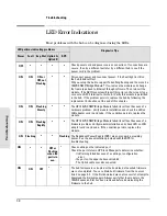
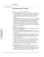
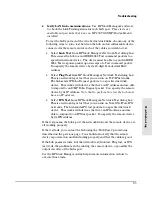
e

Hub Reference

4-2

Summary of Contents for J2415A

Page 1: ...Installation and Reference Guide HP J2415A HP AdvanceStack 100VG Hub 14 ...

Page 2: ......

Page 3: ...HP AdvanceStack 100VG Hub 14 Installation and Reference Guide ...

Page 4: ...ction with the furnishing performance or use of this material Hewlett Packard assumes no responsibility for the use or reliability of its software on equipment that is not furnished by Hewlett Packard For warranty information see the warranty booklet included with the product A copy of the specific warranty terms applicable to your Hewlett Packard product and replacement parts can be obtained from...

Page 5: ...you can connect computers and other devices together on any 100VG IEEE 802 12 network The hub can be used to upgrade your 10 Mbit second Ethernet IEEE 802 3 network that uses unshielded twisted pair cables to a 100 Mbit second network Throughout this manual this hub will be called the Hub 14 HP J2415A AdvanceStack 100VG Hub 14 iii ...

Page 6: ... Ports 12 RJ 45 LAN Downlink Ports Hub Status LEDs LAN Port LEDs Cable Management Bar Transceiver Slots for either Redundant Uplinks or One Uplink One Downlink Front Panel Power Connector 100VG Hub Expansion Slot Back Panel Redundant Power Supply Connector iv ...

Page 7: ...ubs You can chain up to 16 hubs together and manage all of them from one management station Modular Easy to Use Design A 100VG Expansion Slot in the back of the hub for adding optional functionality such as SNMP and bridging capabilities between a 100VG LAN and a 10 Mbit s Ethernet IEEE 802 3 LAN SNMP and remote access server capability for users to dial in and dial out of the LAN SNMP and router ...

Page 8: ......

Page 9: ...password prompt 3 Enter bin to set the transfer type 4 Enter cd pub networking software 5 Enter get filename to transfer the file to your computer and quit CompuServe 1 Login to CompuServe 2 Enter go hpsys 3 Enter lib 7 4 Enter download filename and then quit World Wide Web http www hp com go network_city Select the Support section then Software Downloads and Patches Download the file you need and...

Page 10: ......

Page 11: ...ll 1 13 4 Complete the Hub Network Connections 1 14 Connecting End Nodes 1 14 Connecting Additional Hubs Cascading 1 17 Connecting an Ethernet IEEE 802 3 LAN 1 19 Managing the Hub Cables 1 20 5 Connect a Management Console Optional 1 21 Using a Direct Serial Connection 1 22 Using a Modem Connection 1 23 Using a Data Switching Device 1 25 2 Installing and Using HP Stack Manager Software Description...

Page 12: ...onfiguration 2 10 Network Counters 2 10 Security Features 2 12 Intruder Log 2 14 Hub Reset 2 15 HP Stack Manager Advanced Features 2 16 3 Troubleshooting LED Error Indications 3 2 Troubleshooting Checklist 3 4 Unusual Network Activity 3 6 End to End Network Tests 3 7 Customer Support Services 3 8 Hewlett Packard FTP Library Service 3 9 CompuServe 3 10 HP FIRST Fax Retrieval Service 3 11 HP Network...

Page 13: ...outer 210 Bundle 4 14 Firmware Enhancements 4 15 A Cables and Connectors Recommended Cables A 3 Twisted Pair Cable Connector Pin Outs A 4 Twisted Pair Cable for 100VG LAN Ports A 4 Twisted Pair Cable for the Distributed Management Chain A 5 RS 232 Console Port Connector and Cable Pin Outs A 6 Pin Out for Hub s RS 232 Port Connector A 6 RS 232 C Null Modem Cable supplied with the hub for PC with 9 ...

Page 14: ...B Specifications Safety and Regulatory Statements Index Contents x ...

Page 15: ...tack Hub HP 100VG Network Installation Checklist Hub 14 Installation Summary 1 Install Optional Accessories 2 Verify That the Hub Works 3 Mount the Hub 4 Complete the Hub Network Connections 5 Connect a Management Console Optional ...

Page 16: ...0VG Selectable EISA LAN Adapter HP J2585A 10 100VG Selectable PCI LAN Adapter HP J2585B 10 100VG DeskDirect PCI LAN Adapter 100VG hub s The number of hubs needed depends on the number of HP 100VG end nodes to be networked and the number of ports per hub For example the HP AdvanceStack 100VG Hub 14 provides 12 twisted pair ports Optional modules for your HP AdvanceStack 100VG hub Optional modules p...

Page 17: ... computers or other supported devices Cascade connections to other 100VG hubs Connections to other networks such as a 10 Mbit s Ethernet IEEE 802 3 network requires an HP 100VG SNMP Bridge Module 5 If appropriate connect a management console Windows based PC to the hub or chain of hubs only one hub in a chain needs to have a console connected Run HP Stack Manager or HP Interconnect Manager on the ...

Page 18: ...or the Hub 14 include the following items consult your HP authorized dealer for the most recent list of available accessories 100VG Expansion Slot modules SNMP and 10Base T Bridging HP J2414B 100VG ET SNMP Bridge Module Provides a bridge for connecting a 10 Mbit s Ethernet IEEE 802 3 LAN to your 100VG LAN in your Hub 14 Router HP J3159A AdvanceStack Router 210 Bundle Provides both SNMP and routing...

Page 19: ...ther to form the HP 100VG SNMP Bridge Module If you want remote access server or router capability you need to order those capabilities as separate products and install them into another 100VG hub Contact your HP authorized dealer or reseller for information Wa r n i n g Before installing a module into the 100VG expansion slot unplug the hub Electrical shock or other injury can result if you attem...

Page 20: ...playing the mark of the safety agency that defines the regulations for power cords in your country The mark is your assurance that the power cord can be used safely with the hub N o t e The hub does not have a power switch it is powered on when the power cord is plugged in The hub s power supply automatically adjusts to any AC power source between 100 127 volts and 200 240 volts There are no volta...

Page 21: ...o the 100VG Expansion Slot At Power On All LEDs turn on During Self Test The hub and module self tests require about 20 seconds total After the hub is tested half of the LEDs are momentarily turned on and off Then the remaining LEDs are momentarily turned on and off During the module self test all LEDs are on except Exp Slot LED blinks during module self test After Self Test All LEDs are off excep...

Page 22: ...used If you will be using the cable management bar verify that there is room for the grouped cables to trail out from the side of the hub Allow at least 3 inches 7 6 cm in the front of the hub In the back of the hub allow at least 1 1 2 inches 3 8 cm of space for the power cord Ensure that the HP AdvanceStack hub s do not overload the power circuits wiring and over current protection To determine ...

Page 23: ...ub with the 10 mm M4 screws included in the Accessory Kit The top of each bracket should align with the top of the hub Be careful not to overtighten the screws Note that several different rack mount positions are possible by using the different holes in the bracket and the hub The illustration shows the recommended position for rack mounting to provide the best weight distribution for the hub 10 m...

Page 24: ...asier to stack the other hubs on top 2 As shown below partially install a screw 5 8 inch number 12 24 in each rack upright Ensure that the screws in each upright are at the same level If you are stacking multiple hubs in a single rack and want them to fit tightly the selection of the first screw holes is important In an EIA standard 19 inch telco rack the screw hole pattern is repetitive pairs of ...

Page 25: ... screws be careful not to overtighten 4 Install the other two number 12 24 screws into the upper hole in each bracket Tighten these screws be careful not to overtighten Upper hole in the bracket Lower notch in the bracket Install additional screw Installing the HP AdvanceStack Hub Installing the HP AdvanceStack Hub 1 11 ...

Page 26: ...op hole in the bracket For the next hub above you use the bottom hole and the top notch as shown in the illustration below Continue to alternate notch and hole hole and notch for all hubs to be installed Installing the HP AdvanceStack Hub Installing the HP AdvanceStack Hub 1 12 ...

Page 27: ... mm M4 screws included in the accessory kit 2 Attach the hub to the wall or wood surface with 5 8 inch number 12 wood screws not included 10 mm M4 screws Bracket mounting position for flat mounting on a wall Bracket mounting position for bookshelf style mounting on a wall Plug the power cord into the hub s power receptacle before mounting the hub There may not be enough room to do so after the hub...

Page 28: ...onnect to each LAN port must contain four twisted pairs 8 wires total and must be wired straight through Refer to appendix A for wiring diagrams To connect to a LAN port push the RJ 45 plug on the cable into the RJ 45 jack until the tab on the plug clicks into place To disconnect an RJ 45 plug press the small tab on the plug and pull the plug out of the RJ 45 jack N o t e If you have purchased an ...

Page 29: ...s all 4 pairs of the UTP cable while 10Base T uses only 2 pairs Make sure that all 4 pairs are wired correctly See the included 100VG AnyLAN Technology Guide and appendix A To connect end nodes you can use unbundled or bundled cables An unbundled cable refers to one that contains only four twisted pairs and is used to connect a single end node or device A bundled cable refers to a cable that conta...

Page 30: ...h as a cascaded hub a switch or a LAN analyzer When connecting any promiscuous device with bundled cable you should select the Some Bundled hub cabling feature in HP Stack Manager This is to prevent signal interference crosstalk which can result in unreliable network operation If no promiscuous devices are connected with bundled cables selecting None Bundled will provide the best performance Note ...

Page 31: ...ub use an unbundled cable Use of a bundled cable with a promiscuous device such as a cascaded hub will cause signal interference and result in unreliable operation You can use any or all 100VG LAN downlink ports on the upper level hub to cascade to an uplink port on a 100VG lower level hub Try to minimize the number of levels of cascaded hubs We recommend that you use no more than three levels of ...

Page 32: ...Redundant Links by using either the included HP Stack Manager described in chapter 2 the optional HP Interconnect Manager programs the ASCII console if you have installed an HP J2414B 100VG ET SNMP Bridge Module If your backup link is ever interrupted the downlink LED will blink slowly on the upper level hub When using the above software programs turn off Redundant Links and then turn Redundant Li...

Page 33: ... Fiber Optic Transceiver for 10Base FL HP J2607A Twisted Pair Transceiver for 10Base T HP J2608A ThinLAN Transceiver for 10Base2 HP J2609A AUI Port for external transceivers Refer to the installation instructions supplied with these products for installation and network connection instructions The HP J2414B SNMP Bridge Module installed in the hub s expansion slot provides the bridge functionality ...

Page 34: ...ub s accessory kit are some specialized tie wraps that allow you to wrap the cables and then attach the bundle to the cable management bar as shown in the illustration below In some instances all the cables will not fit inside the post on the cable management bar The specialized tie wrap can be used to bundle the extra cables and hang them on the outside of the post cable management bar specialize...

Page 35: ...Management Chain up to 16 hubs N o t e For a Distributed Management Chain that connects both HP AdvanceStack 10Base T and 100VG hubs the features accessible by HP Stack Manager are hub dependent For HP Stack Manager features that apply to a particular hub refer to the installation and reference manual for that hub For example refer to chapter 2 of this manual for HP Stack Manager features that app...

Page 36: ...2 port s data communication settings using the Communications function in the Settings menu of HP Stack Manager 3 From the main screen click on Connect to establish the communications with the hub or chain of hubs Once the connection is established the hub or chain of hubs will be displayed on the HP Stack Manager s main screen The RS 232 console port is connected to one of the hubs in the chain W...

Page 37: ...nager automatically provides the correct initialization string Use the following illustration to set up your modem connection N o t e To connect the Distributed Management serial port to a modem it is necessary to use a straight through modem cable not included The null modem cable supplied with the hub can be used only for direct connection to a PC Hub 14 PC running Stack Manager External remote ...

Page 38: ...onnectors The cable included with the hub will not work for connecting a modem to the hub 4 Connect the local modem to the serial port on your PC or install it in the PC if it is an internal modem 5 Configure the local modem by using the Local Modem initialization screen in HP Stack Manager 6 From the Communications screen under the Settings menu click on the Modem button 7 Set the Baud Rate and e...

Page 39: ...lows 1 Use the Communications screen under the Settings pull down menu to set up either your direct or modem link communication settings If you need to configure modems refer to Using a Modem Connection described previously 2 Select the Add Terminal Support under the Settings pull down menu This will add several new buttons to the HP Stack Manager main screen that allow you to connect and logon to...

Page 40: ......

Page 41: ...2 Installing and Using HP Stack Manager Software Description Computer Requirements Installing and Starting HP Stack Manager HP Stack Manager Basic Features HP Stack Manager Advanced Features ...

Page 42: ... Chain using the Extension ports on each hub HP Stack Manager can configure and manage any hub on the chain through a single serial or modem link For information on PC to hub connections refer to chapter 1 N o t e HP Stack Manager provides basic management functions for all HP AdvanceStack hubs both 100VG and 10Base T In addition when the hubs are equipped with the appropriate modules HP Stack Man...

Page 43: ...hub For a direct connection a serial cable included with hub to connect a Windows based PC directly to the hub For a remote connection two modems standard modem cables for PC to modem and modem to hub or modem to switching device connections The serial cable included with the hub will not work as a modem cable For chaining multiple hubs together on a Distributed Management Chain Unshielded twisted...

Page 44: ...ore details on using a mouse menus icons buttons online help and other Windows features Using Online Help Specific information about the HP Stack Manager software is included in the online help that accompanies the software For step by step instructions on how to use the HP Stack Manager refer to the online help system To access the HP Stack Manager online help either select Help from the menu bar...

Page 45: ...tion and status LAN traffic statistics 100VG LAN port status 100VG LAN port settings Hub identification Counters Device configuration Security Intruder log Hub reset A description of each basic feature follows N o t e When using HP Stack Manager menu items or functions that are not available for your hub will not be selectable either they will not be displayed or they will be displayed in light gr...

Page 46: ...aches to the hub and then select Local Modem to configure the modem that stays attached to the PC running HP Stack Manager Configuring Data Switching Devices If you will be using HP Stack Manager through a data switching device such as a data switch data terminal controller PBX switch or X 25 PAD you may need to configure the switching device Use the terminal support selection in the Settings menu...

Page 47: ...n the Access button You can use the Hub Panel Graphic to perform configuration tasks and get hub and port status information A toolbar near the top of the graphic contains push button icons that you can click on to perform various functions A message bar at the bottom of the graphic will identify the icons as you pass the mouse cursor over them For more information on the use of the graphic refer ...

Page 48: ...r a particular 100VG LAN port you can view current settings or change settings through the Ports Settings window The Ports Settings window is displayed through the Hub Panel Graphic First select a port by clicking on a LAN port symbol Then click on the Ports Setting icon in the toolbar In the Ports Settings window you can configure each 100VG LAN port as follows enable or disable a port specify tr...

Page 49: ...ger If you are not using the Redundant Uplink feature but would like to use the second uplink connection as a downlink port select 12B from this dialog Note that if you use port 12B as a downlink port port 12A will no longer be active and data will not be transferred through the cable connected to this port Hub Identification If you click on the ID icon in the toolbar of the Hub Panel Graphic you ...

Page 50: ...0VG ET SNMP Bridge Module does not support Token Ring Token Ring cannot be selected if this module is installed in the hub Network Counters LAN port counter values are useful when diagnosing problem conditions If you click on the Counters icon in the Hub Panel Graphic toolbar the Counters window is displayed In the Counters window a summary table lists several counter values for the LAN ports You ...

Page 51: ... frames received with an invalid packet marker Oversized frames received The total number of frames received that were larger than the maximum valid frame size for the VG network frame type Ethernet or Token Ring Transitions into training The number of times the port has entered the training state High priority frames received The count of high priority frames received on the port The count includ...

Page 52: ...ity method is useful for dynamic workgroups that experience frequent changes to end user configuration and require minimal data security protection First Heard Method provides medium port security The first heard method automatically assigns the first address detected on the port as the authorized MAC address This method is useful to quickly identify and authorize end users Under this method the p...

Page 53: ...y of the security options After you have selected how the MAC address is to be authorized you need to specify the type of training allowed Private mode is when an end node or a port on the hub receives only packets specifically addressed to it Private mode is recommended for typical end node to end node communications such as file server to client communications Private mode provides security agai...

Page 54: ...authorized to manage the hub and whether they should receive SNMP event alarms You must authorize at least one network management station to receive the trap notifications by entering the IP or IPX address of the network management station in the authorized managers list Use the Authorized Managers command from the hub s console to configure these addresses This module will forward traps for all u...

Page 55: ...e HP 100VG SNMP Bridge module is interrupted for the duration of the reset process hub configuration information such as ports enabled or disabled remains unchanged The factory reset option is available in the HP Stack Manager Reset dialog box for hubs with an HP 100VG SNMP Bridge Module installed If you are concerned that the hub s configuration may be incorrect and that it may be causing the hub...

Page 56: ...Module is installed in the hub Advanced HP Stack Manager features include the following Advanced embedded agent code that supports SNMP Simple Network Management Protocol for remote management over the network Configuration of IP parameters to allow the hub to be managed from an SNMP network management station on an Internet Protocol network Setting passwords to protect access to the hub through t...

Page 57: ... access to the hub through the RS 232 console port or SNMP based network management stations HP EASE Embedded Advanced Sampling Environment for trend analysis of your network To use EASE you need to buy the optional EASE software Full modem support HP Stack Manager Installing and Using HP Stack Manager 2 17 ...

Page 58: ......

Page 59: ...3 Troubleshooting LED Error Indications Troubleshooting Checklist Unusual Network Problems End to End Network Tests Diagnostic Tests ...

Page 60: ...because of a hardware problem Verify module installation and check the LED on LAN adapter card in end node If the condition persists replace the module ON ON Flashing Rapidly The HP 100VG SNMP Bridge Module failed its self test because of a firmware problem Verify module installation and check LED on LAN adapter card in end node If the condition persists replace the module ON Flashing Flashing The...

Page 61: ... managers list to see if other network management stations need to be added ON Flashing Rapidly Flashing Rapidly A security violation has occurred on a secure port on a managed or unmanged hub because of an address or training capabilities violation With HP Stack Manager HP Interconnect Manager or the ASCII console view the Intrusion Log When you are finished viewing the log you can stop this Secu...

Page 62: ...elected the correct type by reading page 1 16 Exceeding the maximum allowable cable lengths Use up to 100 meters between two nodes for Category 3 and 4 and use up to 200 meters for Category 5 Distributed Management Chain is incorrectly wired If you can t see chained hubs in HP Stack Manager verify your hubs are chained like the illustration on page 1 22 Verify your cables comply with the specifica...

Page 63: ...evices that have an IP address and are able to respond to an ICMP Echo Request packet You specify the remote device by its IP address Note that to perform this test the hub must have an IP address Select IPX Test from HP Stack Manager s Network Test dialog box This is a network layer test that you can run on Novell NetWare IPX networks The hub sends IPX test packets to a specified network device T...

Page 64: ...d packets Make sure that promiscuous ports for example the Uplink port in a hub to hub connection are always connected using unbundled cable Note that this cabling error may result in high Data Error Frame counts on other ports than just the promiscuous port High value for the Priority Promotions counter in HP Stack Manager counters screen There may be excessive high priority traffic on the networ...

Page 65: ...our LAN adapter documentation for more information on available network communication tests Communication tests through the hub can be performed between two 100VG LAN end nodes equipped with 100VG LAN adapters If the HP 100VG hub contains a bridge module you can perform communications tests between an Ethernet IEEE 802 3 LAN end node and a 100VG LAN end node Troubleshooting Troubleshooting 3 7 ...

Page 66: ...he file s from one of these sources you type filename x For example icmupdt x If you can t find the j2415a exe software call your HP authorized dealer HP BBS and World Wide Web The HP BBS phone number is 208 344 1691 Set your modem communication settings to parity N none data bits 8 stop bits 1 baud rates 300 1200 2400 4800 9600 or 14400 From the BBS you can download files and learn about HP netwo...

Page 67: ...onymous 3 At the password prompt enter your internet e mail address 4 Change directories cd pub networking software 5 At the ftp prompt set the transfer type to binary bin 6 List the contents of the directory dir 7 Retrieve the file by entering get filename e g get j2414b exe 8 Quit the FTP session by entering quit 9 Extract the file e g j2414b x Troubleshooting Troubleshooting 3 9 ...

Page 68: ...ne lines for transmitting and receiving data CompuServe is available 24 hours a day seven days per week The participants pay a monthly fee for this service To get the latest agent firmware from CompuServe follow these steps 1 Login to CompuServe 2 Type go hpsys 3 Type lib 7 4 Type download filename e g download icmupdt exe 5 Log off CompuServe 6 Extract the file e g icmupdt x Troubleshooting 3 10 ...

Page 69: ...r fax machine or touch tone phone and press 1 Outside the U S and Canada Dial 1 208 344 4809 from your fax machine and press 9 To receive a list of currently available documents enter document number 19941 The information you requested will be sent to you by return fax HP Network Phone In Support NPS Call your HP Authorized Dealer or the nearest HP Sales and Support Office In addition the HP Netwo...

Page 70: ...electricity Observe these precautions when removing and installing the modules When handling the module first touch a grounded metal surface or wear an antistatic wrist strap that is attached to grounded metal To prevent generating static electricity minimize your movement around the work area or work in an antistatic work area Handle the module carefully at all times Avoid flexing it or touching ...

Page 71: ...4 Hub Reference Front of the Hub Back of the Hub Cascading Hubs Chained Hub Operation Serial Port Communications Hub Management Security Features Optional Modules Firmware Enhancements ...

Page 72: ...le is installed the ASCII console On This hub is currently being accessed by HP Stack Manager or the ASCII console Exp Slot green On An optional module is properly installed in the hub s back panel slot Off An optional module is not installed Flashing Slowly The module is performing its self test after hub power on or a reset If the rate of flashing increases and the flashing continues for more th...

Page 73: ... provided with the RPS for troubleshooting Activity green Off No network traffic is present on the hub Flashing ON while a packet is being transmitted on any port Normally the LED appears to flicker In heavy traffic it may appear to be on all the time Cascade green Off No cascading of hubs has been detected On This hub is cascaded with another hub either through the Uplink port or through one or m...

Page 74: ...Management Chain is accomplished in two ways Out of Band Management From a Windows based PC running HP Stack Manager connected to an RS 232 Console Port on one of the hubs in the chain In Band Management From a network management station running a supported network management utility For in band management an Expansion Slot module that supports SNMP Simple Network Management Protocol must be insta...

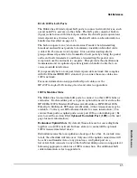
Page 75: ...n on supported LAN port cables see the HP 100VG AnyLAN Technology Guide and refer to appendix A 100VG Modular Slots The Hub 14 has two modular LAN ports to connect to other 100VG hubs or end nodes Each modular port accepts an optional transceiver such as the HP J3028A 100VG Twisted Pair Transceiver Module or HP J3030A 100VG Fiber Optic Multimode ST Transceiver Module Other transceivers may be avai...

Page 76: ...d Optional Downlink Port 12B This port can be used to create a fiber optic backbone to another Hub 14 by installing fiber optic transceivers into both hubs If you do not want to use redundant uplinks and would rather use the modular port as a flexible media downlink port you can connect a cable to the port labeled Uplink B or 12B Before or after you connect the cable to this port use HP Stack Mana...

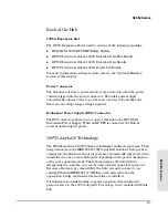
Page 77: ...is hub to the HP J2962A Redundant Power Supply When an HP RPS is connected the Hub 14 receives uninterrupted power 100VG AnyLAN Technology The HP AdvanceStack 100VG hubs are intelligent multiport repeaters Their design is based on the IEEE 802 12 100VG AnyLAN standard Data packets coming into the hub from any of its ports are automatically regenerated and transmitted to one or more LAN ports depen...

Page 78: ...e Hub Management Out of Band Management Out of band management refers to the ability to manage an HP AdvanceStack hub or chain of hubs from a Windows based PC running HP Stack Manager or from an ASCII console For hubs on a Distributed Management Chain the PC can be connected to the RS 232 console port of any hub in the chain HP Stack Manager is a Windows program that serves as the console interfac...

Page 79: ...ters end to end so multiple wiring closets can be managed from a single location for example a single PC running HP Stack Manager Note that this is not a network connection it is only a management connection between the hubs For information on the cables used on a Distributed Management Chain refer to appendix A HP AdvanceStack hubs use a Distributed Management Protocol to pass command and data co...

Page 80: ...installed The port provides full V 22bis modem line control when connected to a modem link for remote access to the hub or chain of hubs In Band Management In band management refers to the ability to manage an HP AdvanceStack hub or chain of hubs from a network management station that is running a supported network management utility such as HP Interconnect Manager The management station must be c...

Page 81: ...ate cascade and any device modes you can specify three levels of address security on a single port or all ports on the hub When a security violation occurs you can specify whether an alarm is sent to the network management station See chapter 2 for details Devices are not allowed to pass training until their configuration matches the port s permission The hubs will see a security violation occur i...

Page 82: ...ridge capability The modules supports SNMP Simple Network Management Protocol and has extended management features The SNMP Bridge module is inserted into the 100VG Expansion Slot of the hub When the Expansion Slot cover is in place the module will not be visible However the Exp Slot LED on the front panel provides information on the status of the module For installation instructions refer to the ...

Page 83: ... you need more than two ports the HP Dial A LAN 4A has four RS 232 ports for connecting up to four external modems This module can also be used in an ISDN environment with terminal adapters Both the 2 Port and 4 Port modules support these features Access speeds available to 115 2 Kbps Throughput speeds available are dependent on line quality type of data transmitted and the remote node s ability t...

Page 84: ... 048 Mbit s This port allows HP Point to Point PPP V 25 bis dial up ISDN SMDS frame relay and LAPB X 25 connections to other routers over point to point or switched circuits An internal Ethernet 802 3 LAN port through which the router module communicates with the hub The router provides both bridging and routing capabilities and supports the following routing services Internet Protocol TCP IP prot...

Page 85: ...he hub s RS 232 Distributed Management port For more information about the HP Router 210 Module see its accompanying documentation or you can view the information on HP s web page http www hp com go network_city Firmware Enhancements Hewlett Packard continually improves its products When firmware enhancements are made to the HP AdvanceStack hubs you will be able to easily update them with the new ...

Page 86: ......

Page 87: ...A Cables and Connectors Recommended Cables Twisted Pair Cable Connector Pin Outs RS 232 Console Port Connector and Cable Pinouts ...

Page 88: ...ed to follow the minimum pin out will function correctly N o t e Incorrectly wired cabling is the most common cause of problems for LAN communications HP recommends that you work with a qualified LAN cable installer for assistance with your cabling requirements These topics are discussed Recommended HP cables Twisted pair cable connector pin outs Console connector and cable pin outs For cables to ...

Page 89: ...eiver the HP 28641B ThinLAN Transceiver and the HP 28683A fiber Optic Transceiver These transceivers can be attached directly to the AUI connector on the AUI port module Connecting a PC to the hub s RS 232 console port Connecting a PC to the hub s RS 232 port 9 pin male RS 232 C 9 pin female to 9 pin female null modem or crossover cable RS 232 C cable provided with the hub HP p n 5182 4794 25 pin ...

Page 90: ...code and pair configuration for an 100VG LAN cable unbundled that conforms to the EIA TIA 568B wiring standard for a straight through cable N o t e Pins 1 and 2 must be wired to a twisted pair Pins 3 and 6 must be wired to a twisted pair Pins 4 and 5 must be wired to a twisted pair Pins 7 and 8 must be wired to a twisted pair Straight through cable Pair 2 blue white white blue Pair 4 brown white w...

Page 91: ...must conform to AT T 258A not USOC See Twisted Pair Cable Pin Assignments later in this chapter for a listing of the signals used on each pin N o t e Pins 4 and 5 must be wired to a twisted pair Pins 1 2 3 6 7 and 8 are not used in this application although they may be wired in the cable The maximum total length of all the extension cables in a chain is 185 meters blue white white blue Straight th...

Page 92: ...ect a PC to be used as the console To connect a modem to the hub use a standard RS 232 C modem cable This section provides pin assignment information for the cables you can use on the hub s RS 232 management console port Pin Out for Hub s RS 232 Port Connector PIN US CCITT DIN 1 DCD 109 M5 2 Rx 104 D2 3 Tx 103 D1 4 DTR 108 S1 5 GND 102 6 DSR 107 M1 7 RTS 105 S2 8 CTS 106 M2 9 RI 125 M3 Cables and ...

Page 93: ...Connector PC end 9 pin female Hub end 9 pin female 1 1 DCD 2 2 Rx 3 3 Tx 4 4 DTR 5 5 GND 6 6 DSR 7 7 RTS 8 8 CTS 9 9 RI 3 Wire Cable for Direct Console Connection PC end 9 pin female Hub end 9 pin female 2 2 Rx 3 3 Tx 5 5 GND Cables and Connectors Cables and Connectors A 7 ...

Page 94: ...em end 25 pin male Hub end 9 pin male Signal 2 3 Tx 3 2 Rx 4 7 RTS 5 8 CTS 6 6 DSR 7 5 GND 8 1 CD OR DCD 20 4 DTR 22 9 RI 23 DRS typically on V 24 European modems not connec ted Cables and Connectors Cables and Connectors A 8 ...

Page 95: ...B Specifications ...

Page 96: ... Frequency range 50 60 Hz 50 60 Hz Environmental Operating Non Operating Temperature 0 C to 55 C 32 F to 131 F 40 C to 70 C 40 F to 158 F Relative humidity non condensing 15 to 95 at 40 C 104 F 90 at 65 C 149 F Maximum altitude 4 6 km 15 000 ft 4 6 km 15 000 ft Connectors The RJ 45 twisted pair ports are compatible with the IEEE 802 12 100VG AnyLAN standard The RS 232 C console port conforms to V ...

Page 97: ...sions FCC part 15 Class A CISPR 22 Class A EN 55022 Class A VCCI Level I Immunity See the Declaration of Conformity at the end of this guide Complies with Canadian EMC Class A requirements Specifications Specifications B 3 ...

Page 98: ......

Page 99: ...Safety and Regulatory Statements ...

Page 100: ...t s input wiring terminals power cord or supplied power cord set Whenever it is likely that the protection has been impaired disconnect the power cord until the ground has been restored For LAN cable grounding If your LAN covers an area served by more than one power distribution system be sure their safety grounds are securely interconnected LAN cables may occasionally be subject to hazardous tran...

Page 101: ...limentation ou le cordon de raccordement fourni avec le produit Lorsque cette protection semble avoir été endommagée débrancher le cordon d alimentation jusqu à ce que la mise à la terre ait été réparée Mise à la terre du câble de réseau local si votre réseau local s étend sur une zone desservie par plus d un système de distribution de puissance assurez vous que les prises de terre de sécurité soi...

Page 102: ... den Netzkabeln oder dem mit Strom belieferten Netzkabelsatz voraus Sobald Grund zur Annahme besteht daß der Schutz beeinträchtigt worden ist das Netzkabel aus der Wandsteckdose herausziehen bis die Erdung wiederhergestellt ist Für LAN Kabelerdung Wenn Ihr LAN ein Gebiet umfaßt das von mehr als einem Stromverteilungssystem beliefert wird müssen Sie sich vergewissern daß die Sicherheitserdungen fes...

Page 103: ...pure al set cavo d alimentazione fornito con il prodotto Ogniqualvolta vi sia probabilità di danneggiamento della protezione disinserite il cavo d alimentazione fino a quando il collegamento a terra non sia stato ripristinato Per la messa a terra dei cavi LAN se la vostra LAN copre un area servita da più di un sistema di distribuzione elettrica accertatevi che i collegamenti a terra di sicurezza s...

Page 104: ...ato el cable de alimentación o el juego de cable de alimentación suministrado Si existe la probabilidad de que la protección a tierra haya sufrido desperfectos desenchufar el cable de alimentación hasta haberse subsanado el problema Puesta a tierra del cable de la red local LAN Si la LAN abarca un área cuyo suministro eléctrico proviene de más de una red de distribución de electricidad cerciorarse...

Page 105: ...Safety Information Japanese Safety Information Safety Information Japanese 7 ...

Page 106: ...interference in which case the user at his own expense will be required to take whatever measures may be required to correct the interference If this equipment causes interference to radio reception which can be determined by unplugging the power cord from the equipment try these measures Re orient the receiving antenna Relocate the equipment with respect to the receiver Plug the equipment and rec...

Page 107: ... HP AdvanceStack 100VG Hub 14 complies with ISO IEC Guide 22 and EN 45014 The declaration identifies the product the manufacturer s name and address and the applicable specifications that are recognized in the European community Safety Information Declaration of Conformity 9 ...

Page 108: ......

Page 109: ...Index ...

Page 110: ...serial port 1 4 A 3 A 7 Cascade LED 4 3 cascading hubs 1 17 4 8 uplink port 4 5 chaining 1 22 cable wiring diagram A 5 chained hub operation 4 9 connecting a management console 1 21 displaying chained hubs 2 7 checklist HP 100VG network installation 1 2 hub installation 1 3 communications settings HP Stack Manager 2 6 CompuServe obtaining files from 3 10 connections 100VG network 1 14 4 5 cable ma...

Page 111: ... the hub LEDs 4 2 reset button 4 4 ftp obtaining files from HP 3 9 H help in HP Stack Manager 2 4 See also online help high priority operation enabling in HP Stack Manager 2 10 LAN traffic statistics 2 8 Hourly support calling for 3 11 HP 100VG SNMP Bridge module See SNMP Bridge HP Dial A LAN Bundles 4 13 HP FIRST FAX Retrieval Service using 3 11 HP FTP Library Service using 3 9 HP Router 210 Bund...

Page 112: ... 3 2 flash rate 4 3 verifying hub operation 1 7 level 1 hub See cascading hubs link test 3 5 lower level hub See cascading hubs M management console 1 21 4 10 communications settings 2 6 See also console port direct serial connection 1 22 through data switching device 1 25 managing the hub 4 4 4 8 distributed management 4 9 modems cables A 8 communications settings 2 6 management console connectio...

Page 113: ...setting 2 10 security and 4 11 promiscuous mode 100VG uplink port 4 6 cabling requirements 1 16 HP Stack Manager setting 2 10 security and 4 11 R rack mounting 1 9 Redundant Uplink Ports from HP Stack Manager 2 7 reset factory 2 16 factory effect 2 15 reset button 4 4 using HP Stack Manager 2 15 RJ 45 connectors connecting chained hubs 1 22 4 4 connecting network devices 1 14 4 5 wiring diagram A ...

Page 114: ...ver modules Ethernet IEEE 802 3 1 19 installation 1 5 troubleshooting IPX test 3 5 link test 3 5 Ping test 3 5 testing the ports and links 3 5 unusual network activity 3 6 troubleshooting checklist 3 4 twisted pair cable 100VG LAN cables A 4 Distributed Management Chain A 5 twisted pair ports connection procedures 1 14 using bundled unbundled cables 1 16 4 5 U unbundled cable 1 16 for LAN connecti...

Page 115: ......
Page 116: ...Technical information in this document is subject to change without notice Copyright 1996 Hewlett Packard Company Printed in Singapore 2 96 Manual Part Number J2415 90021 J2415 90021 ...

Reviews: